Image display method and image display apparatus

a technology of image display and display method, applied in the direction of instruments, television systems, static indicating devices, etc., can solve the problems of inability to display images without, disadvantage of known top-view image display systems, and difficulty in displaying images withou

Active Publication Date: 2009-06-25
ALPINE ELECTRONICS INC
View PDF2 Cites 44 Cited by
  • Summary
  • Abstract
  • Description
  • Claims
  • Application Information

AI Technical Summary

Benefits of technology

[0024]An advantage of the invention is to prevent any part of an image from disappearing due to a change in the attitude of a camera, and to prevent any part of an image, which was not shown before the change, from appearing due to the same reason.
[0025]In a first aspect of the invention, an image display method displays a combined image by capturing images at areas surrounding a vehicle using a plurality of cameras and then combines the images captured by the plurality of cameras into a top-view image that shows the vehicle observed from a certain virtual point of view taken above the vehicle. The method includes a) calculating a plurality of displacement vectors for a plurality of points taken on the images when a certain load changes the attitude of a camera, and b) determining each image borderline between two adjacent images in such a manner that a difference in the directions of displacement vectors in the neighborhood of each image borderline between two adjacent images does not exceed a predetermined angle.
[0026]The method further includes clipping an image portion that is demarcated by two image borderlines out of the image captured by each of the plurality of cameras so as to generate the combined image.
[0027]The method also includes a) pre-storing correspondences between camera attitudes and sets of image clip positions, which are determined on the basis of the image borderlines, for each camera, b) measuring an actual camera attitude, and c) clipping an image area portion in accordance with a set of image clip positions that corresponds to the measured actual camera attitude for each camera to generate the combined image.
[0028]The method additionally includes a) pre-storing correspondences between the number of occupants of a vehicle and sets of image clip positions, which are determined on the basis of the image borderlines, for each camera b) detecting the actual number of the occupants of the vehicle, and c) clipping an image area portion in accordance with a set of image clip positions that correspond to the detected actual number of the occupants of the vehicle for each camera to generate the combined image.
[0029]The method also includes a) pre-storing correspondences between the total load weight of a vehicle, that is, the aggregate weight of occupants and luggage excluding the weight of the vehicle itself, and sets of image clip positions, which are determined on the basis of the image borderlines, for each camera, b) detecting the actual total load weight of the vehicle, and c) clipping an image area portion in accordance with a set of image clip positions that corresponds to the detected actual total load weight of the vehicle for each camera to generate the combined image.

Problems solved by technology

A top-view image display system of the JP '334 has a disadvantage in that the position of some part of an image is shifted to the outside of a display area boundary that was set in the process of distortion correction, and thus disappears due to such a change in the attitude of a camera.
A top-view image display system of the related art has a disadvantage in that if any object is located in this disappearance area, it is not possible or is very difficult to display the image without any missing portions.
Known top-view image display systems are disadvantageous because some part of an image disappears near an image borderline due to a change in the attitude of a camera, which occurs when a vehicle is loaded.

Method used


Image

  • Image display method and image display apparatus
  • Image display method and image display apparatus
  • Image display method and image display apparatus

Examples


Embodiment Construction

A. Overview of the Invention

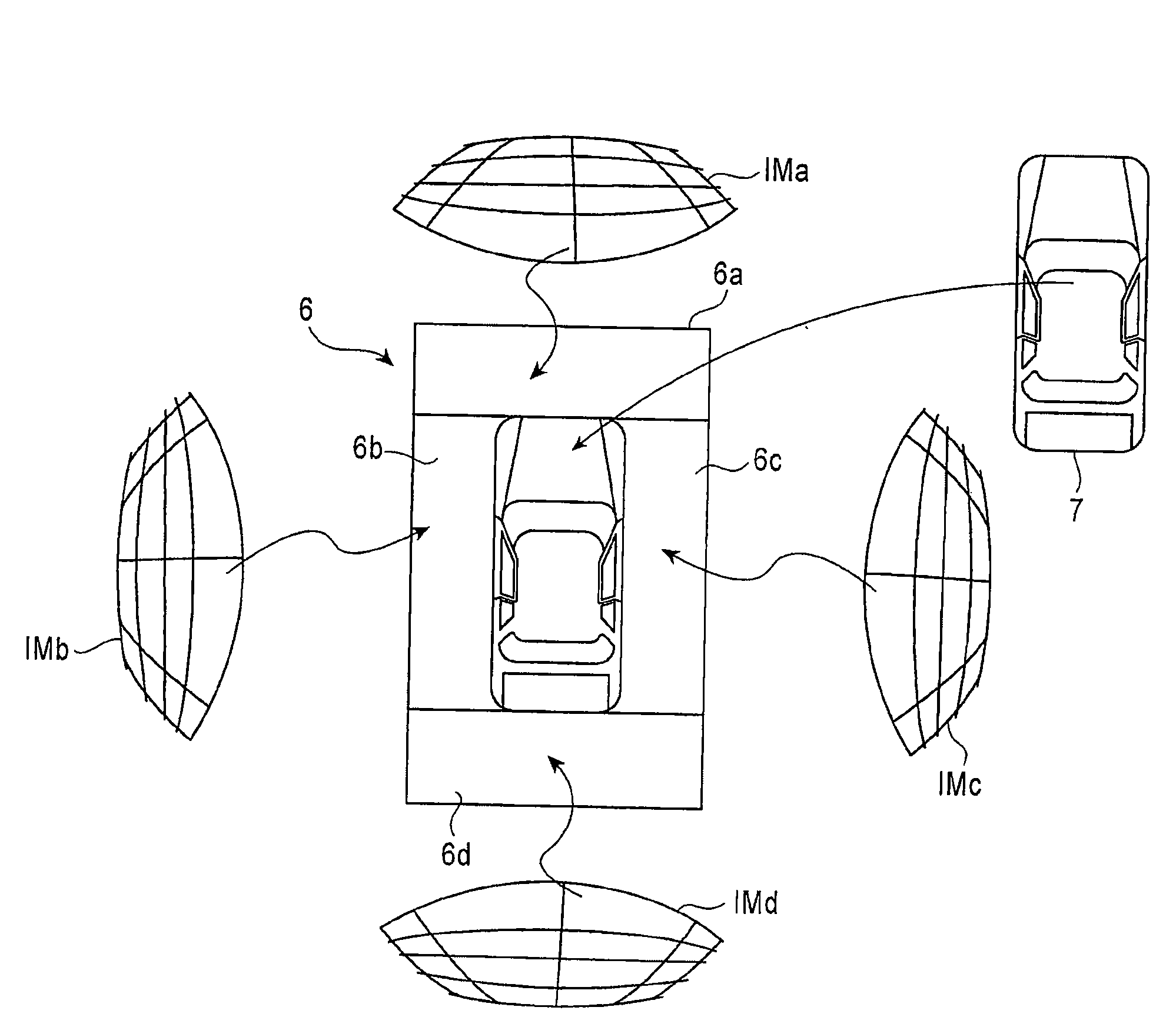
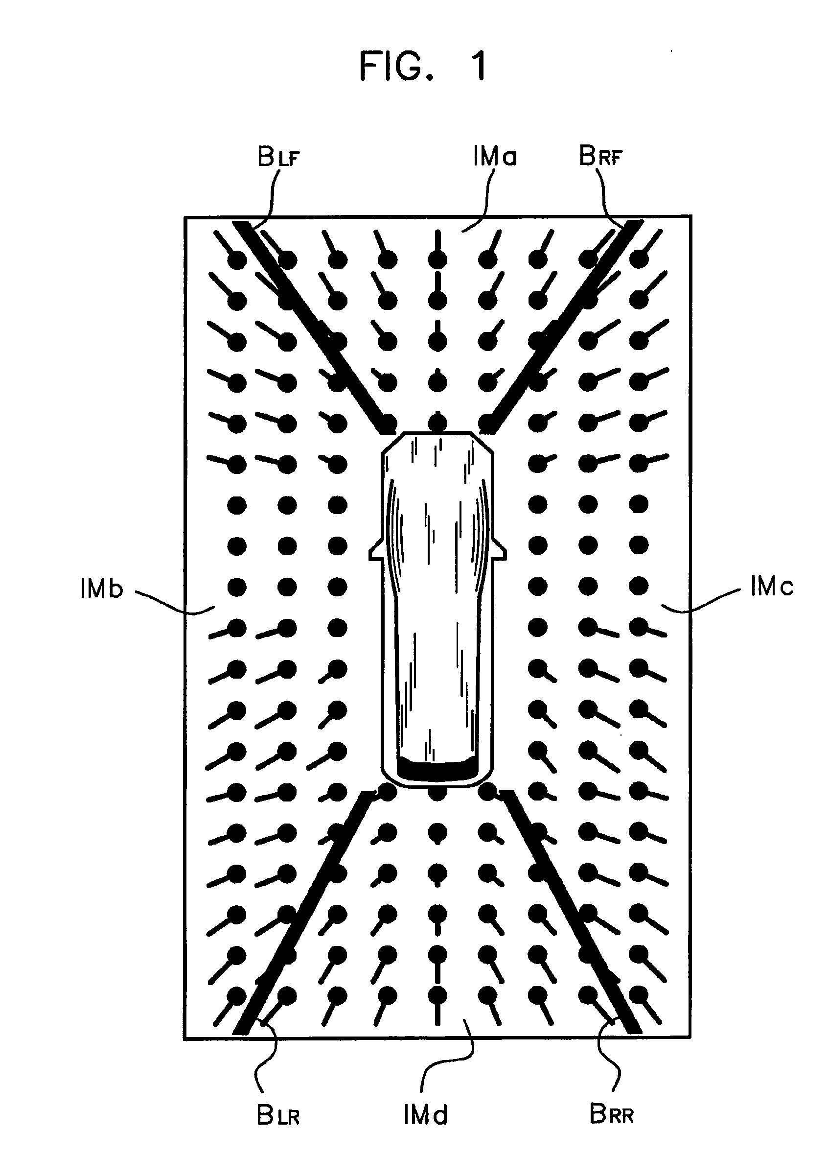
[0065]FIG. 1 schematically illustrates a plurality of displacement vectors for a plurality of points taken on the distortion-corrected fish-eye images IMa, IMb, IMc, and IMd, which are captured by the fish-eye lens cameras 1a, 1b, 1c, and 1d (FIG. 18B), respectively. The displacement vectors are generated as a result of the application of a certain load that changes the attitude of a camera on the vehicle, which is hereafter denoted as CAR. In this drawing, the position of each point is denoted by a black circle. Each short line segment that extends from the black circle indicates both the direction of a displacement vector, and the magnitude of the displacement vector.

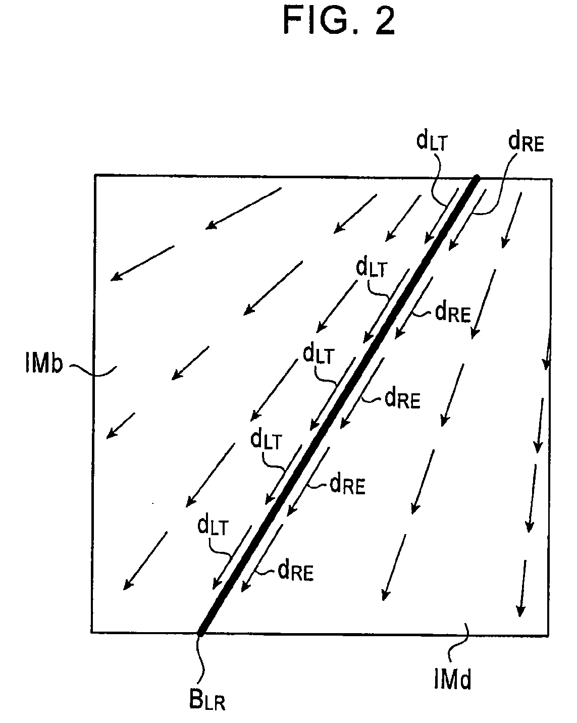
[0066]In FIG. 1, the reference numeral BLR denotes an image borderline between the left image IMb and the rear image IMd. The reference numeral BLF denotes an image borderline between the left image IMb and the front image IMa. The reference numeral BRR denotes an image borderline between t...


PUM


Abstract

An image display method for displaying a combined image by capturing images at areas surrounding a vehicle includes a) calculating a plurality of displacement vectors for a plurality of points taken on images captured by a plurality of cameras upon the application of a load that changes the attitude of a camera on the vehicle, and b) determining each image borderline between two adjacent images such that a difference in the directions of displacement vectors in the neighborhood of each image borderline between two adjacent images does not exceed a predetermined angle.

Description

PRIORITY CLAIM[0001]This application claims the benefit of Japanese Patent Application No. 2007-328570, filed on Dec. 20, 2007, and which is incorporated by reference herein in its entirety.BACKGROUND[0002]1. Field of the Invention[0003]The present invention relates to an image display method and an image display apparatus. In particular, the invention relates to an image display method for displaying a combined image that shows a vehicle observed from a virtual point of view taken above the vehicle. A plurality of cameras capture peripheral images at areas around the vehicle. The peripheral images are combined to form the combined image for display.[0004]2. Description of the Related Art[0005]Known driving support systems may assist a driver to park a car in a garage and / or in a parking space. Known system may display a top-view image, as described in Japanese Patent No. 3,300,334 (“JP '334”). In the top-view image display of JP '334, images are captured at areas surrounding a vehi...

Claims


Application Information

Patent Timeline
Patent Type & Authority Applications(United States)
IPC IPC(8): H04N7/18G09G5/00
CPCH04N7/181B60R1/00
Inventor IMAMURA, KOSUKE
Owner ALPINE ELECTRONICS INC
Why Eureka
Try Eureka