Magnetic tape, magnetic tape apparatus, servo pattern recording apparatus, magnetic tape producing method, and magnetic tape recording method

a technology of servo pattern recording and magnetic tape, which is applied in the direction of maintaining head carrier alignment, digital recording, magnetic tape, etc., can solve the problems of high sensitivity and increase in track density, and achieve the effect of accurate recording/reproduction

Active Publication Date: 2009-06-25
SONY CORP
View PDF15 Cites 121 Cited by
  • Summary
  • Abstract
  • Description
  • Claims
  • Application Information

AI Technical Summary

Benefits of technology

[0019]For recording the data as described above, under the presupposition that the servo patterns are recorded in advance, the reproducing channel located on the same bump as the recording head usually reproduces the plurality of servo patterns first at a start of the recording (no recording current is supplied during reproduction) to thus control the position of the head, and the recording operation is started thereafter. Specifically, a recording current is supplied to the recording head to record data, and the recording current is stopped after a certain time period (right before next servo pattern). The reproducing head of the same bump then reproduces the next servo pattern to detect the positional information of the head, and again returns to the recording immediately thereafter. Hereinafter, the recording, reproduction, and head position control are repeated until the recording is completed. During recording, the reproducing head of the downstream bump is used to perform read-after-write (or read-while-write). In other words, in a case of positioning the recording head using the reproducing head located on a bump different from that of the recording head during recording, there arises a problem that due to the tilt of the running of the magnetic tape, the position of the recording track is deviated and the recording head thus enters a region of the adjacent track (may overwrite data on the already-recorded adjacent track or data may be overwritten by the adjacent track in the recording afterwards). Meanwhile, in the embodiment of the present invention, by alternately using the recording head and the reproducing head located on the same bump time-divisionally for data recording and detection of the position of the recording head, it becomes possible to reproduce the servo patterns using the reproducing head disposed closer to (and inversely-attached to) the recording head and record the data at the correct position while avoiding the problem that is caused when the magnetic tape is run with a tilt. Moreover, the problem of crosstalk from the recording head to the reproducing head during recording can be suppressed.
[0069]As described above, according to the embodiments of the present invention, there can be provided a magnetic tape to / from which data can accurately be recorded / reproduced, a servo pattern recording apparatus for the magnetic tape, a magnetic tape apparatus capable of detecting deformation (expansion / contraction in width and longitudinal directions) information and tilt information of the magnetic tape, a method of producing the magnetic tape, and a recording method of the magnetic tape.

Problems solved by technology

However, an increase in the track density is known to raise the following issues.
Specifically, there arise issues on how to detect tracking information with high sensitivity and, with respect to a generally-used two-bump-type head, how to cope with a tilt in running of the magnetic tape, how to cope with a deformation of the magnetic tape (in width and longitudinal directions), and how to make a head channel spacing smaller.

Method used


Image

  • Magnetic tape, magnetic tape apparatus, servo pattern recording apparatus, magnetic tape producing method, and magnetic tape recording method
  • Magnetic tape, magnetic tape apparatus, servo pattern recording apparatus, magnetic tape producing method, and magnetic tape recording method
  • Magnetic tape, magnetic tape apparatus, servo pattern recording apparatus, magnetic tape producing method, and magnetic tape recording method

Examples


Embodiment Construction

[0090]Hereinafter, an embodiment of the present invention will be described with reference to the drawings.

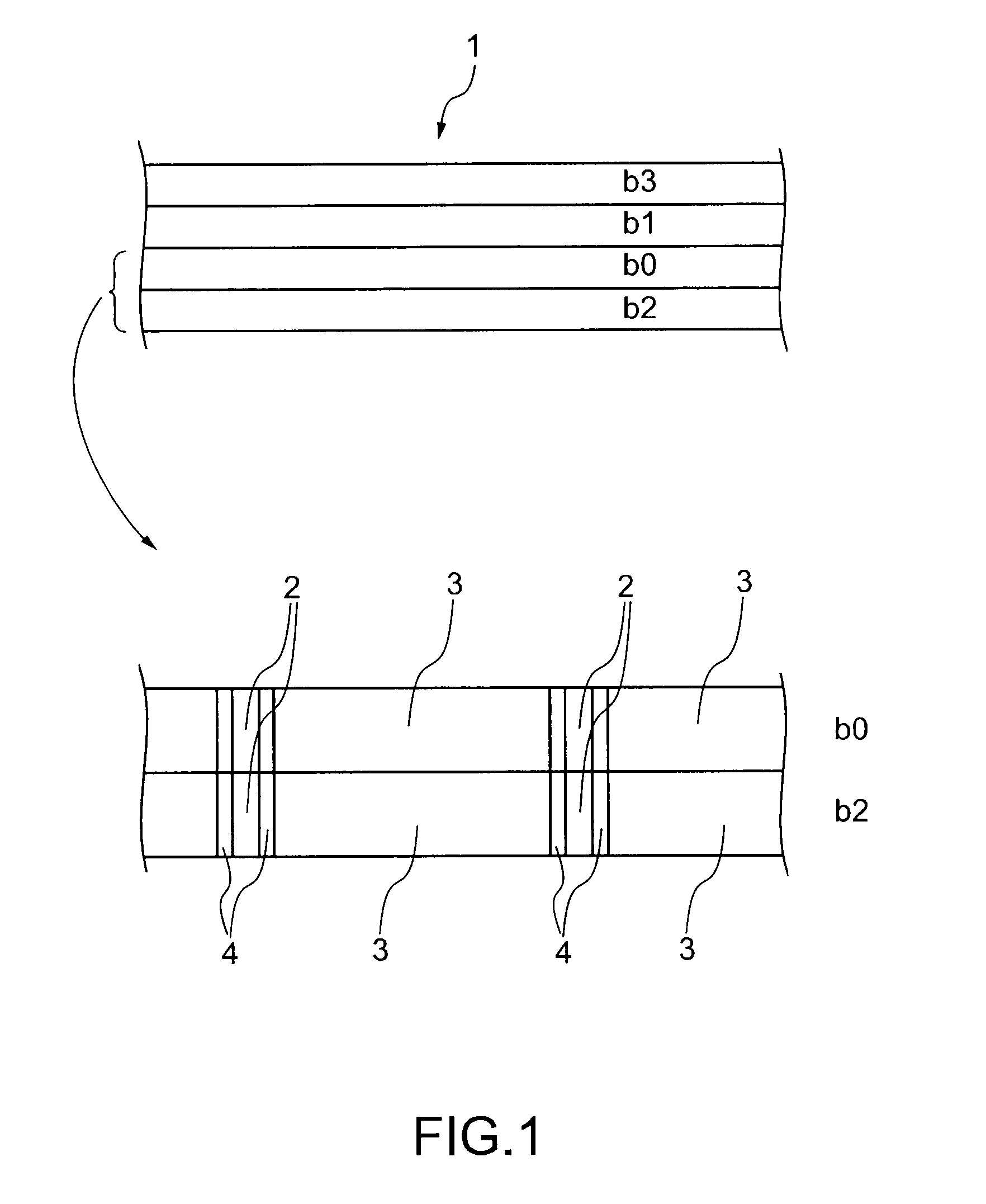
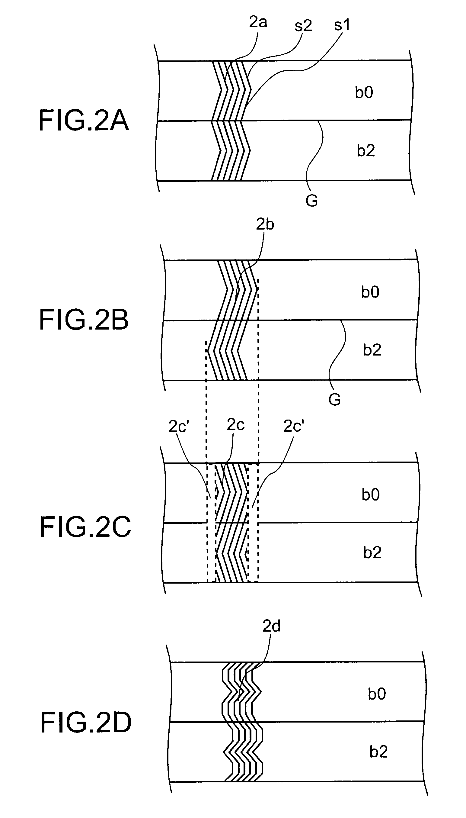
[0091]FIG. 1 is a plan view showing a magnetic tape 1 according to an embodiment of the present invention. FIGS. 2A to 2D are plan views each showing an example of a servo pattern 2 of the magnetic tape 1 shown in FIG. 1. FIG. 3 shows diagrams for illustrating a principle in detecting information on a head position of a magnetic tape apparatus, deformation of the magnetic tape 1, and tilt of the magnetic tape 1.

[0092]As shown in FIG. 1, the magnetic tape 1 includes a plurality of (e.g., 4) data bands b0 to b3, servo patterns 2 formed along a longitudinal direction of the magnetic tape 1 with an interval provided between each of the servo patterns, each of the servo patterns formed across a full width of the data bands b0 to b3, a data burst 3 disposed between the servo patterns 2, and a guard space 4 disposed between the servo pattern 2 and the data burst 3. An integral multipl...


PUM

PropertyMeasurementUnit
azimuth anglesaaaaaaaaaa
magneticaaaaaaaaaa
widthaaaaaaaaaa

Abstract

Provided is a magnetic tape that includes a data band, including servo patterns, data, and a guard space. The servo patterns is formed along a longitudinal direction of the magnetic tape with an interval provided between each of the servo patterns, each of the servo patterns formed across a full width of the data band. The data is disposed between the servo patterns. The guard space is disposed between each of the servo patterns and the data.

Description

CROSS REFERENCES TO RELATED APPLICATIONS[0001]The present invention contains subject matter related to Japanese Patent Application JP 2007-327102 filed in the Japanese Patent Office on Dec. 19, 2007, the entire contents of which being incorporated herein by reference.BACKGROUND OF THE INVENTION [0002]1. Field of the Invention[0003]The present invention relates to a magnetic tape, a servo pattern recording apparatus for the magnetic tape, a magnetic tape apparatus such as a linear magnetic tape apparatus, a method of producing the magnetic tape, and a recording method of the magnetic tape.[0004]2. Description of the Related Art[0005]Track-following servo control of the related art involves, for example, providing a longitudinal servo track previously recorded between longitudinal data track groups, the servo track being parallel to the data track groups, so that the servo track can be read by one or a plurality of servo heads, adjusting a position of the head or tape in a tape width ...

Claims


Application Information

Patent Timeline
Patent Type & Authority Applications(United States)
IPC IPC(8): G11B5/584G11B5/78
CPCG11B5/584
Inventor TAKAYAMA, JUNKUMAGAI, SEIJI
Owner SONY CORP
Why Eureka
Try Eureka