Control of emitted light from luminaire

Active Publication Date: 2009-06-25
GONZALEZ DAVID
View PDF4 Cites 7 Cited by
  • Summary
  • Abstract
  • Description
  • Claims
  • Application Information

AI Technical Summary

Benefits of technology

[0007]The present invention addresses the above need by providing apparatus and method of mitigating unwanted optical effects arising from the use of supplementary luminaires used to illuminate objects being photographed. In broad terms, the novel approach is to interpose

Problems solved by technology

The use of supplementary luminaires may provide the requisite level of light, but may also be subject to certain unwanted effects.
One possible unwanted effect is that of too much light impinging upon the subject, especially upon one portion of an object being photographed.
As an illustration, a photographer may wish to photograph a large object such as an automobile, only to find that a supplemental luminaire creates overly bright lighting which disrupt the final image.
The overly bright lig

Method used


Image

  • Control of emitted light from luminaire
  • Control of emitted light from luminaire
  • Control of emitted light from luminaire

Examples


Embodiment Construction

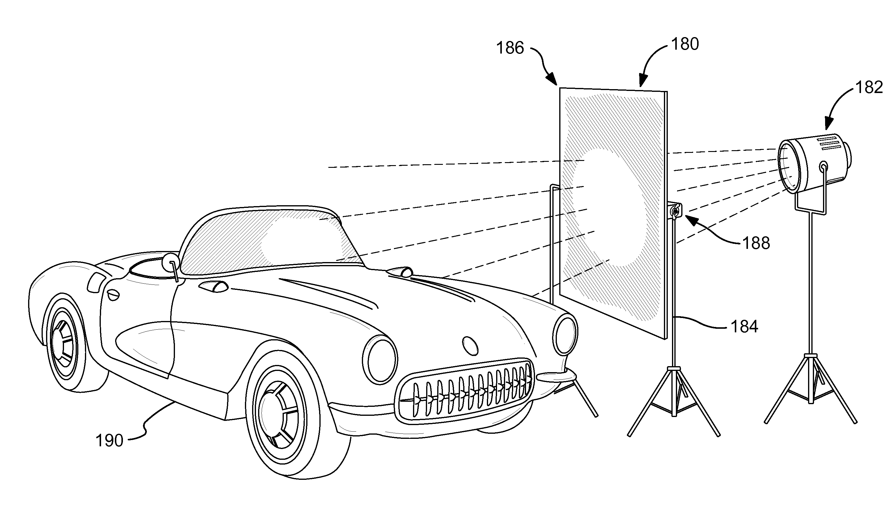
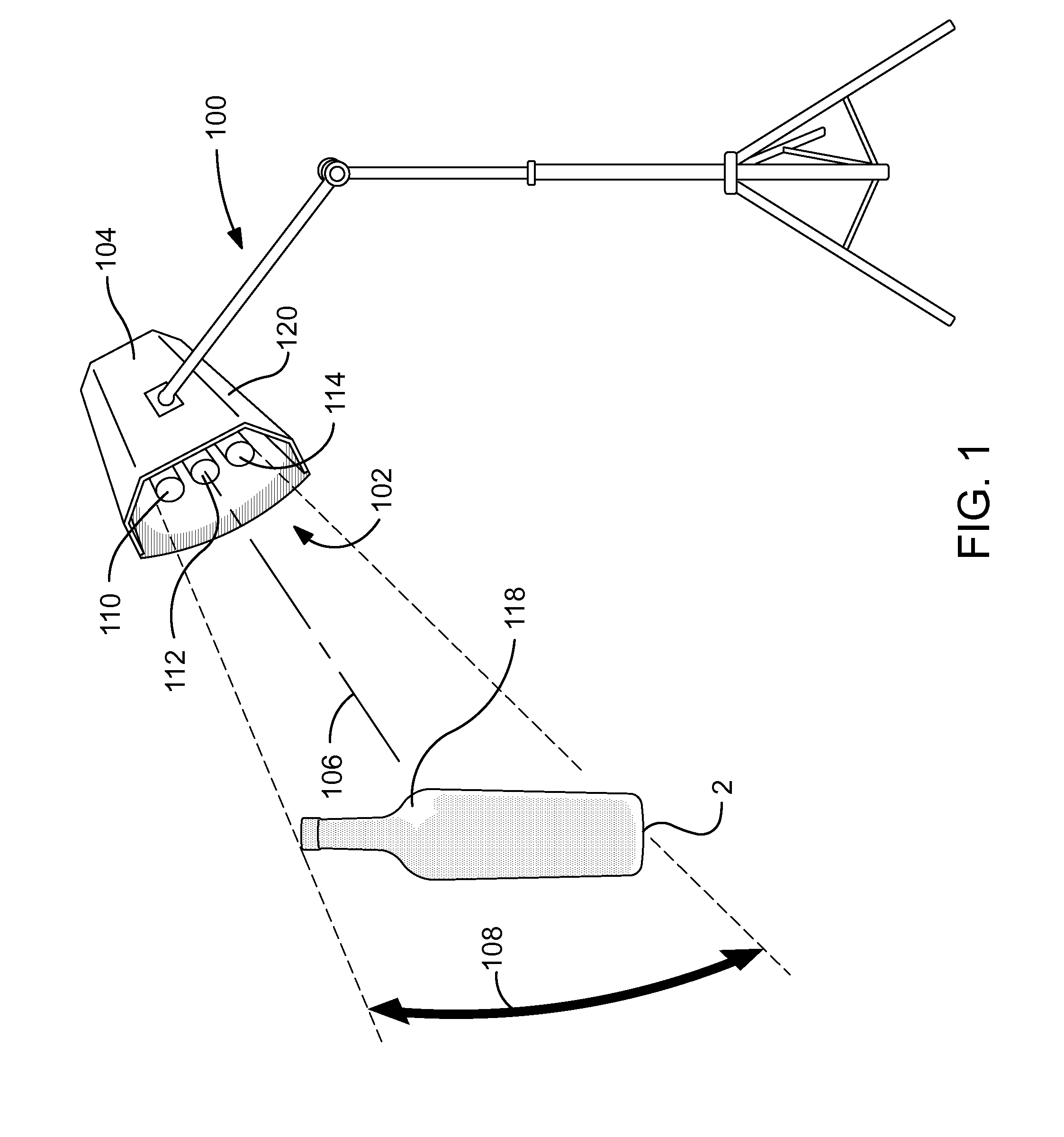
[0023]FIG. 1 of the drawings shows a combination of a luminaire 100 for illuminating subject matter 10 of photography, and a mask 102 disposed to mitigate undesired optical effects visited upon the subject matter, which undesired optical effects arise from the luminaire 100. The undesirable effects may include the reflection shown in FIG. 8 and discussed prior.

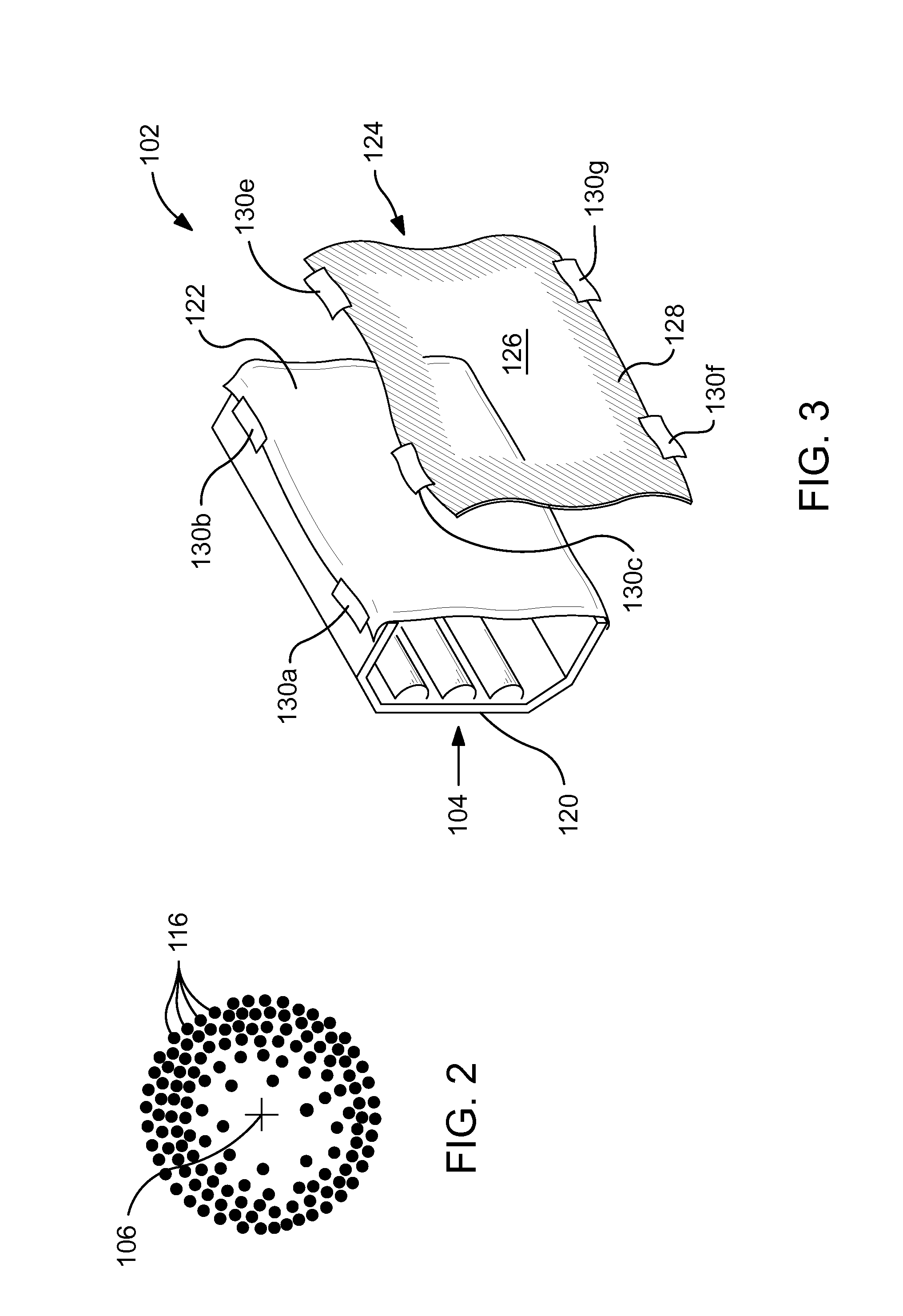
[0024]The luminaire 100 may comprise a lighting head 104 bearing at least one light source disposed to project light therefrom along a projection area having a central axis 106 and an adjacent zone surrounding the central axis 106. The adjacent zone is represented by an arrow 108, but will be understood to extend in two orthogonal dimensions rather than merely in one direction as visually suggested by the arrow 108. Illustratively, the light source may comprise three fluorescent tubes 110, 112, 114 arrayed parallel to one another as is frequently done with conventional luminaires such as the luminaire 4 of FIG. 1. Such an arra...


PUM


Abstract

Method and apparatus for attenuating unwanted aspects of lighting from a luminaire which is disposed to illuminate an object or objects being photographed. A light attenuating mask is disposed between the luminaire and the object or objects. The light attenuating mask may diffuse, obstruct, or otherwise modify projected light such that light intensity is diminished, unwanted reflections of the luminaire are suppressed, or other aspects of the light are altered. The mask may attach to the luminaire or may be free standing and separate therefrom.

Description

CROSS-REFERENCE TO RELATED APPLICATIONS[0001]This application claims the benefit of the filing dates under 35 USC 119(e) to U.S. Provisional Application Ser. No. 61 / 014,884, filed Dec. 19, 2007, and U.S. Provisional Application Ser. No. 61 / 074,215, filed Jun. 20, 2008 the contents of which are incorporated herein by reference.FIELD OF THE INVENTION[0002]The present invention relates to control of light which is being intentionally projected from a luminaire onto an object or surface for the purpose of illuminating the object or surface. More specifically, the invention relates to controlling light originating from the luminaire so that harshness of the light, and unintended lighting effects which result from the luminaire are mitigated.BACKGROUND OF THE INVENTION[0003]The field of photography frequently uses supplemental intentional illumination of the subject of the photography. As employed herein, photography will be taken in its broadest context, encompassing still photography, d...

Claims


Application Information

Patent Timeline
IPC IPC(8): G03B15/02F21V1/00
CPCG03B15/02
Inventor GONZALEZ, DAVID
Owner GONZALEZ DAVID
Why Eureka
Try Eureka