Image forming apparatus

Inactive Publication Date: 2009-06-25
RICOH KK
View PDF14 Cites 20 Cited by
  • Summary
  • Abstract
  • Description
  • Claims
  • Application Information

AI Technical Summary

Benefits of technology

[0019]In view of the above-described situation, the present disclosure provides an image forming apparatus capable of effectively using housing-internal space to output

Problems solved by technology

Such a configuration reduces the height of the image forming apparatus, resulting in downsizing the apparatus as a whole.
Further, when a plurality of sheets is stacked on the post-processing tray, a precedent sheet may need to pass through a sheet reverse unit before a subsequent sheet is fed, resulting in a reduction in productivity.
Since there is a certain distance between the she

Method used


Image

  • Image forming apparatus
  • Image forming apparatus
  • Image forming apparatus

Examples


Embodiment Construction

[0034]In describing embodiments illustrated in the drawings, specific terminology is employed for the sake of clarity. However, the disclosure of this patent specification is not intended to be limited to the specific terminology so selected and it is to be understood that each specific element includes all technical equivalents that operate in a similar manner and achieve similar results.

[0035]Below, illustrative embodiments are described with reference to the drawings. First, to facilitate understanding of the disclosure, structure and operation of an image forming apparatus according to an illustrative embodiment are described with reference to FIGS. 1 and 2.

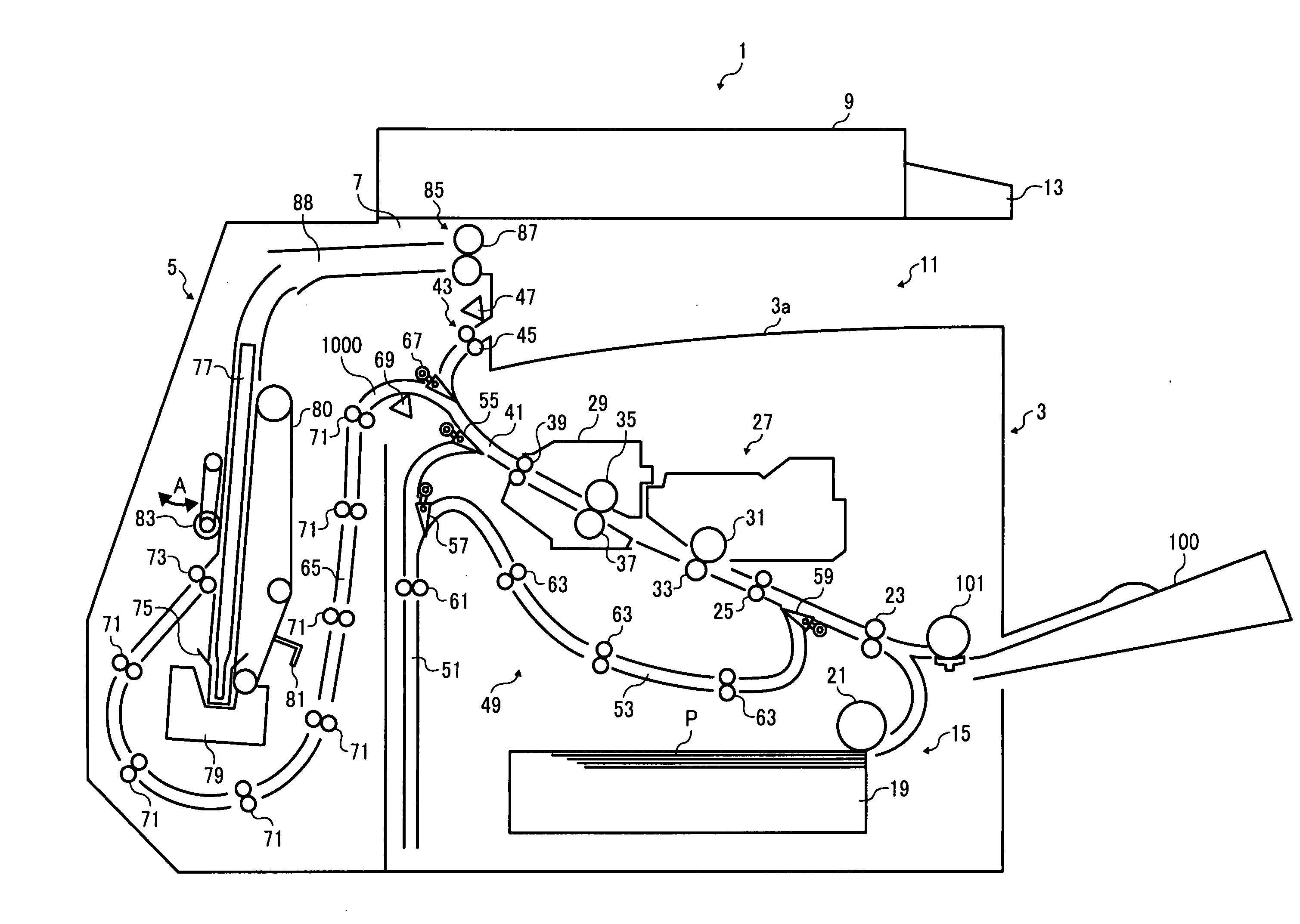
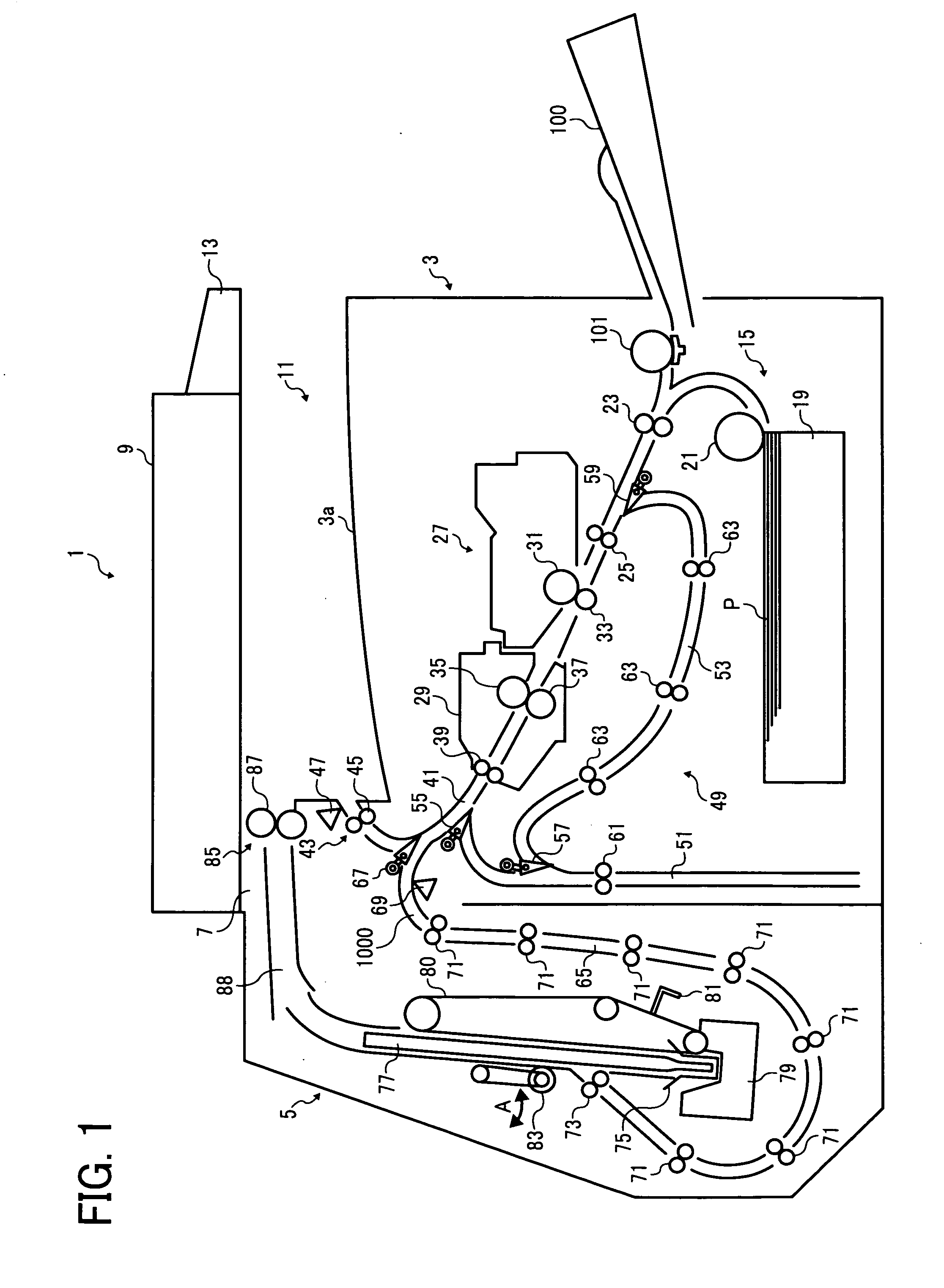
[0036]As illustrated in FIG. 1, an image forming apparatus 1 according to the present illustrative embodiment includes an apparatus body 3 serving as an image forming section and a post-processing unit 5 serving as a post-processing section integrally or detachably mounted at one side, for example, a rear side (opposite to an...


PUM


Abstract

An image forming apparatus includes an image forming unit, a first sheet stack portion, a sheet output section, and a post processing unit. The image forming unit forms an image on a sheet. The first sheet stack portion is provided at an upper face of the image forming unit. The sheet output section outputs the sheet on which the image is formed by the image forming unit from one side of the image forming apparatus to the first sheet stack portion. The post processing unit is provided adjacent to a lateral side of the image forming unit at an upstream side of the sheet output section to execute post processing on the sheet. A sheet subjected to post-processing by the post-processing unit is output to the first sheet stack portion from the same direction as a sheet not subjected to post-processing by the post-processing unit.

Description

CROSS-REFERENCE TO RELATED APPLICATIONS[0001]The present patent application claims priority pursuant to 35 U.S.C. §119 from Japanese Patent Application Nos. 2007-332791, filed on Dec. 25, 2007, 2007-337962, filed on Dec. 27, 2007, and 2008-265648, filed on Oct. 14, 2008 in the Japan Patent Office, the entire contents of each of which are hereby incorporated herein by reference.BACKGROUND OF THE INVENTION[0002]1. Field of the Invention[0003]The present invention relates to an image forming apparatus, such as a copier, a printer, a facsimile machine, a plotter, a multifunctional device capable of performing several of the foregoing functions, or the like, and more specifically, to an image forming apparatus capable of outputting both a sheet subjected to post-processing and a sheet not subjected to post-processing to a so-called housing-internal space formed within the space occupied by the body of the image forming apparatus.[0004]2. Description of the Background[0005]Image forming a...

Claims


Application Information

Patent Timeline
IPC IPC(8): G03G15/00G03G21/16
CPCG03G15/6552G03G2215/00894G03G2215/00421
Inventor SHIRAKI, TAKAMASAKAWAMURA, KAZUSHIGEOHTA, YOSHIHIDEANDOH, TAKAYUKIOGAWA, MASATOTAKAHASHI, TAKUJIFUJIOKA, TETSUYAYOUDA, YASUNOBUHATAYAMA, KOHJI
Owner RICOH KK
Why Eureka
Try Eureka