Weapon robot with situational awareness

a situational awareness and robot technology, applied in the field of robots, can solve the problems of difficulty for the operator to decipher where the robot is in relation to the operator, how the robot is orientated, and its direction of travel, and achieve the effect of reducing the likelihood of the operator

Active Publication Date: 2009-06-25
FOSTER-MILLER
View PDF42 Cites 65 Cited by
  • Summary
  • Abstract
  • Description
  • Claims
  • Application Information

AI Technical Summary

Benefits of technology

[0006]It is a further object of this invention to provide such a system which provides situational awareness for the operator.
[0007]It is a further obje...

Problems solved by technology

Cameras on the robot can be used to show the operator objects within the field of view of the robot, but it can be difficult f...

Method used


Image

  • Weapon robot with situational awareness
  • Weapon robot with situational awareness
  • Weapon robot with situational awareness

Examples


Embodiment Construction

[0028]Aside from the preferred embodiment or embodiments disclosed below, this invention is capable of other embodiments and of being practiced or being carried out in various ways. Thus, it is to be understood that the invention is not limited in its application to the details of construction and the arrangements of components set forth in the following description or illustrated in the drawings. If only one embodiment is described herein, the claims hereof are not to be limited to that embodiment. Moreover, the claims hereof are not to be read restrictively unless there is clear and convincing evidence manifesting a certain exclusion, restriction, or disclaimer.

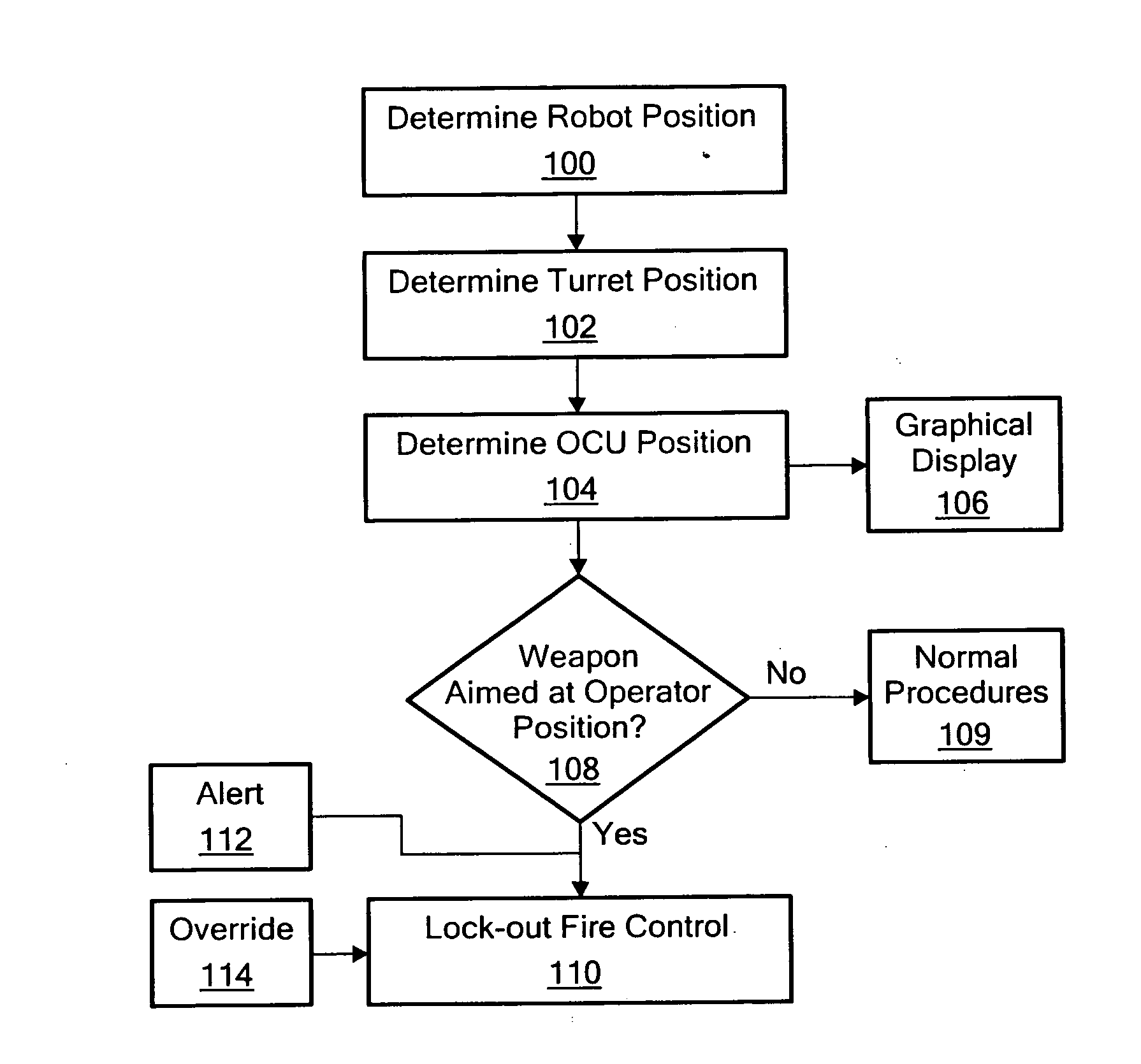
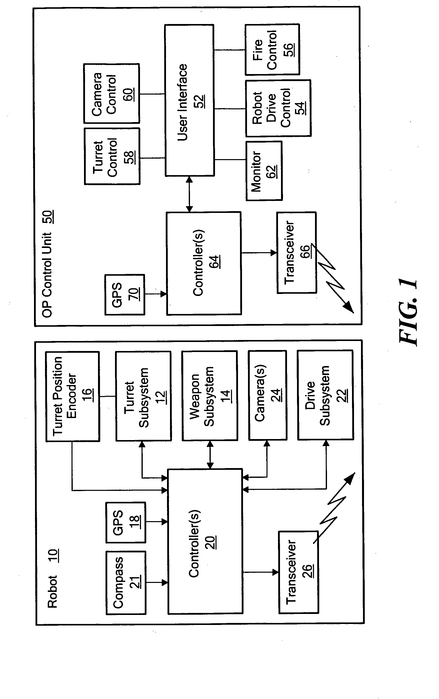
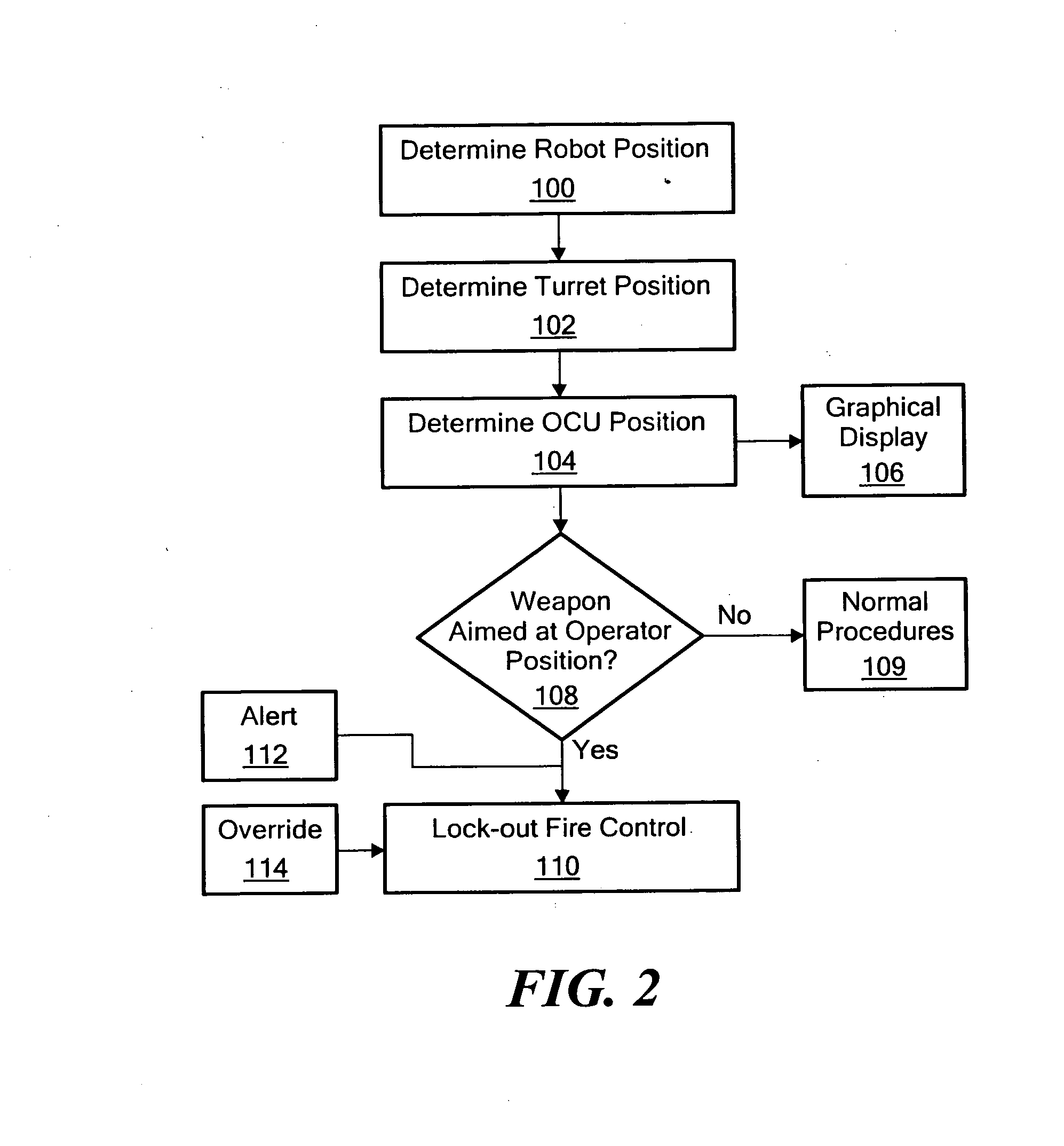
[0029]Robot 10, FIG. 1 in accordance with an example of this invention, typically mobile and remotely controlled, includes a turret subsystem 12 for a weapon mounted thereto. In the embodiment shown in FIG. 2, turret 12 can rotate 360° and pitch weapon 14 up 60° and down to 20°. Devices such as encoders 16, FIG. 1 keep trac...


PUM


Abstract

A mobile, remotely controlled robot includes a turret subsystem, a robot controller subsystem configured to control the robot, control the turret, and fire the weapon, a robot navigation subsystem configured to determine the position of the robot, a turret orientation determination subsystem, and a robot communications subsystem for receiving commands and for transmitting robot position data and turret orientation data. An operator control unit includes a user interface for commanding the robot, the turret, and the weapon. An operator control unit communications subsystem transmits commands to the robot and receives robot position data and turret orientation data from the robot. An operator control unit navigation subsystem is configured to determine the position of the operator control unit. An operator control unit controller subsystem is responsive to the robot position data, the turret orientation data, and the operator control unit position and is configured to determine if the weapon is aimed at the operator control unit within a predetermined fan angle.

Description

FIELD OF THE INVENTION[0001]The subject invention relates to robotics and to remotely controlled mobile robots equipped with weapons.BACKGROUND OF THE INVENTION[0002]The notion of a mobile remotely controlled robot with a weapon mounted thereto is intriguing. The robot could be maneuvered into a hostile situation and the weapon fired by an operator positioned out of harms way. For the deployment of such a robot, several safety concerns need to be met. Co-pending U.S. patent application Ser. No. 11 / 732,875 filed Apr. 5, 2007 details various systems and methods for ensuring the weapon on a robot is not fired unless the operator so intends.[0003]In the field, the robot typically begins at a position proximate the operator using an operator control unit (OCU) to maneuver the robot. As the robot is controlled by the operator using the operator control unit (OCU), the robot may be maneuvered out of sight of the operator. Indeed, the operator and the OCU may also move from the original sta...

Claims


Application Information

Patent Timeline
IPC IPC(8): G05D1/00G01C21/00
CPCG05D1/0038G05D1/0044G05D1/0094G05D2201/0209G08C17/00F41A17/08G08C2201/50F41H7/005F41G3/165F41G3/22F41G5/06G08C2201/30
Inventor DEGUIRE, DANIEL R.BRUCK, KURTYOUNG, JOHNKIRILLOV, ALEXCHUNG, JAMES
Owner FOSTER-MILLER
Why Eureka
Try Eureka