Sock

a technology of socks and soles, applied in the field of socks, can solve the problems of inability to achieve a sufficient spring-like function, body to feel languid, feet to tire,

Active Publication Date: 2009-07-02
OKAMOTO INDS +1
View PDF18 Cites 85 Cited by
  • Summary
  • Abstract
  • Description
  • Claims
  • Application Information

AI Technical Summary

Benefits of technology

[0015]Socks are described below that may allow for maintaining a normal shape of both the longitudinal plantar arch and the transverse plantar arch formed by the bones of the foot, the ligaments, and a group of plantar muscles. This may be accomplished by securely positioning compression areas at a suitable position on the foot, without the compression areas slipping when the sock is worn. The invention may include any of the following aspects in various combinations and may also include any other aspect described below in the written description or in the attached drawings. In one aspect, the sock comprises a first compression area which raises the compressive force in a wale direction from a position behind a toe area of a sole portion of the sock to a position which includes the boundary between an arch portion and a heel portion. The sock further includes a second compression area provided on a periphery of the sock to raise the compressive force in a course direction at a position behind the toe area, and a third compression area provided on the periphery to raise the compressive force in a course direction at an ankle portion. A fourth compression area is provided on the periphery of the sock to raise the compressive force in a course direction from a position which includes the boundary between an arch portion and a heel portion to a position at the base of the instep portion.

Problems solved by technology

However, when the plantar ligaments and the group of plantar muscles stretch excessively due to vigorous exercise and walking for long periods of time, it becomes impossible to maintain the arch shapes of the longitudinal plantar arch P1 and the transverse plantar arch P2 and a shock-absorbing effect is not sufficiently achieved during walking, thus it becomes impossible to achieve a sufficient spring-like function, consequently causing the feet to tire and the body to feel languid.
Furthermore, since the bottoms of the feet are unable to absorb shock, this can affect the joints of the feet, the knees, and the groin.
In severe cases, this excessive stretching may affect the hips and the shoulders, making it necessary to undergo treatment at a hospital.
However, the sock of Japanese Laid-Open Patent Application No. 2005-3125121 gives priority to preventing the development of conditions such as poor blood circulation and chilblain, and does not provide an elastic expanding member for the entire periphery in the course direction of the sock.
Therefore, since the position of the elastic expanding member slips while the sock is being worn, there is the problem in that the sock does not impart a continuous compressive force at the desired position, making it impossible to achieve much of an advantageous effect, even if an elastic expanding member is provided with the aim of restoring the transverse arch and the longitudinal arch.
However, since the sock of Japanese Laid-Open Patent Application No. 2006-225833 imparts an upward force on the upper portion of the calcaneus from the position of the arch due to the highly elastic areas in an upper diagonal direction, but no consideration was given to protecting and restoring the transverse plantar arch and the sock fails to protect the longitudinal plantar arch by lifting the arch straight upward and to restore the longitudinal plantar arch to its original shape.
In addition, in the sock of Japanese Laid-Open Patent Application No. 2006-225833, since the highly elastic areas which are divided right and left by the arch portion are continued again from the back of the heel, when the sock is worn, it is possible to prevent it from slipping forward from the arch position, but a problem exists in that it is impossible to prevent the position of the highly elastic areas to slip backward from the arch position.
Accordingly, since the position of the highly elastic areas slips while wearing the sock, it is impossible to continuously raise the arch.

Method used


Image

  • Sock
  • Sock
  • Sock

Examples


example

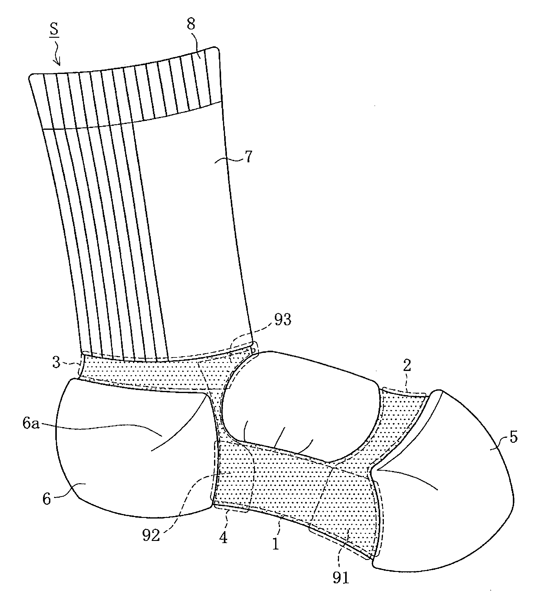
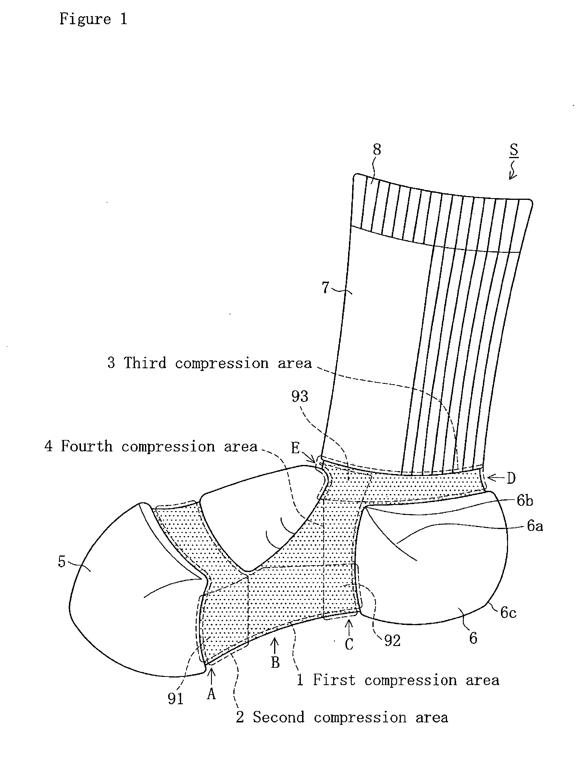
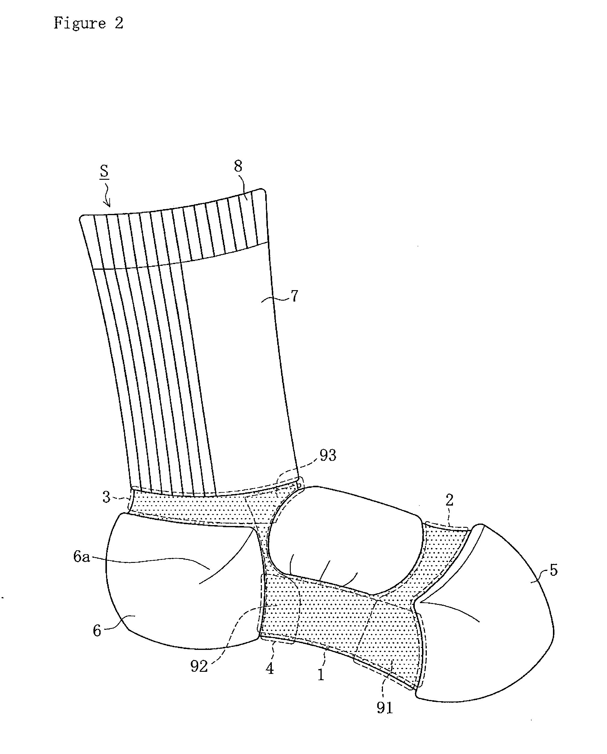
[0057]The sock of the present invention is described in further detail below based on the following example. FIG. 1 is a lateral view of a sock of an embodiment of the present invention for the right foot as seen from the side of the big toe. FIG. 2 is a lateral view of the same sock as seen from the side of the little toe. FIG. 3 is a view of the same sock as seen from the side of the sole portion. FIG. 4 is a view of the same sock as seen from the side of the instep portion. FIG. 5 is a drawing illustrating the direction of compression for the first through the fourth compression areas.

[0058]As shown in FIG. 1, a sock S of this example is provided with a first compression area 1 which raises the compressive force in a wale direction from a position A behind the toe area of a sole portion of the sock to a position C which includes the boundary between an arch portion B and a heel portion 6, a second compression area 2 provided on the periphery to raise the compressive force in a co...


PUM


Abstract

A sock is provided having a first compression area 1 which raises the compressive force in a wale direction from a position A behind the toe area of a sole portion of the sock to a position C which includes the boundary between an arch portion B and a heel portion 6, a second compression area 2 provided on the periphery to raise the compressive force in a course direction at the position A behind the toe area, a third compression area 3 provided on the periphery to raise the compressive force in a course direction at an ankle portion D, and a fourth compression area 4 provided on the periphery to raise the compressive force in a course direction from the position C which includes the boundary between the arch portion B and the heel portion 6 to a position E at the base of the instep portion. The advantageous effect of protecting and restoring the shape of the longitudinal plantar arch is produced by the various compression areas, thereby stabilizing the position of the various compression areas while the sock is worn.

Description

RELATED APPLICATIONS[0001]The present application claims priority to Japanese Patent Application Number 2007-336224, filed Dec. 27, 2007, the entirety of which is hereby incorporated by reference.TECHNICAL FIELD[0002]The present invention relates to a sock which maintains a normal shape of a longitudinal plantar arch and a transverse plantar arch formed by bones of the foot, ligaments, and a group of plantar muscles, by securely positioning a compression area which raises the compressive force in a desired direction at a suitable position on the foot, thereby making it possible to prevent a variety of foot injuries.BACKGROUND ART[0003]FIG. 9 shows the configuration of the bones of a right human foot as seen from the bottom side of the foot. FIG. 11 shows the configuration of the bones of a right human foot as seen from the instep side. As shown in FIG. 9 and FIG. 11, the bones of the human foot consist of the tarsals N3, which include the calcaneus Q1, the talus Q2, the navicular Q3...

Claims


Application Information

Patent Timeline
Patent Type & Authority Applications(United States)
IPC IPC(8): A43B17/00A61F13/06
CPCA61F13/064D04B1/265A61F13/067D04B1/02
Inventor ARAKI, TAKAHIROYANAGISAWA, YUKOMAKIKAWA, MASAAKI
Owner OKAMOTO INDS
Why Eureka
Try Eureka