End stop for slide fastener

a technology for fasteners and end stops, which is applied in the direction of snap fasteners, slide fasteners, press-button fasteners, etc., can solve the problems of increasing costs and inducing uneconomical conditions, and achieves excellent function, effective pressing and deformation, and facilitate crimping work.

Active Publication Date: 2009-07-02
YKK CORP
View PDF5 Cites 7 Cited by
  • Summary
  • Abstract
  • Description
  • Claims
  • Application Information

AI Technical Summary

Benefits of technology

[0015]The projecting portion provided on the inner face of the base portion accurately positions the core portion of the fastener tape disposed within the accommodation portion, and facilitates crimping work by the leg portions. In addition, when the leg portions are crimped to hold the core portion disposed within the accommodation portion, a gap portion provided between the projecting portion and the root of each leg portion allows the core portion along the entire length and across the entire width of the accommodation portion to be deformed and can capture the deformed portion easily.
[0016]Further, the projecting portion is formed continuously so as to project into the accommodation portion or intermittently so as to project into the accommodation portion, or is formed in substantially the same thickness as the fastener tape. Consequently, the core portion can be positioned accurately in the accommodating portion and the core portion within the accommodation portion can be easily and effectively pressed and deformed.
[0017]Additionally, the protruded portion is formed on the inner face of the leg portion such that it projects into the accommodation portion, or the projection portion is provided such that it projects into the accommodation portion. Alternatively, both of the protruded portion and the projection portion are formed such that they project into the accommodating portion. As a result, the core portion disposed within the accommodation portion can be captured securely by the protruded portion and the projection portion and nipped strongly, thereby completely preventing the top end stop from deviating on the core portion.
[0018]When the bottom end stop is formed by providing the leg portions on both faces of the base portion in a bent manner so that the accommodation portions are provided on both sides, the bottom end stop achieves an excellent function. Further the leg portions are provided on a single face of the base portion so that the accommodation portion is formed on a single side, and the locking piece projecting sideways is provided at the front end on one side of the leg portion or the protruded portion is formed at the root of the locking piece on the inner face of the leg portion such that the protruded portion projects into the accommodation portion. Accordingly, a top end stop having an excellent function can be produced, this top end stop can stop a slider easily, and additionally, the top end stop bites into the core portion of the fastener tape strongly, so that it never deflect in position even if the slider collides violently, thereby ensuring an excellent quality as the top end stop.

Problems solved by technology

As a result, cost increases to induce an uneconomical condition and it is also inconvenient.

Method used


Image

  • End stop for slide fastener
  • End stop for slide fastener
  • End stop for slide fastener

Examples


first embodiment

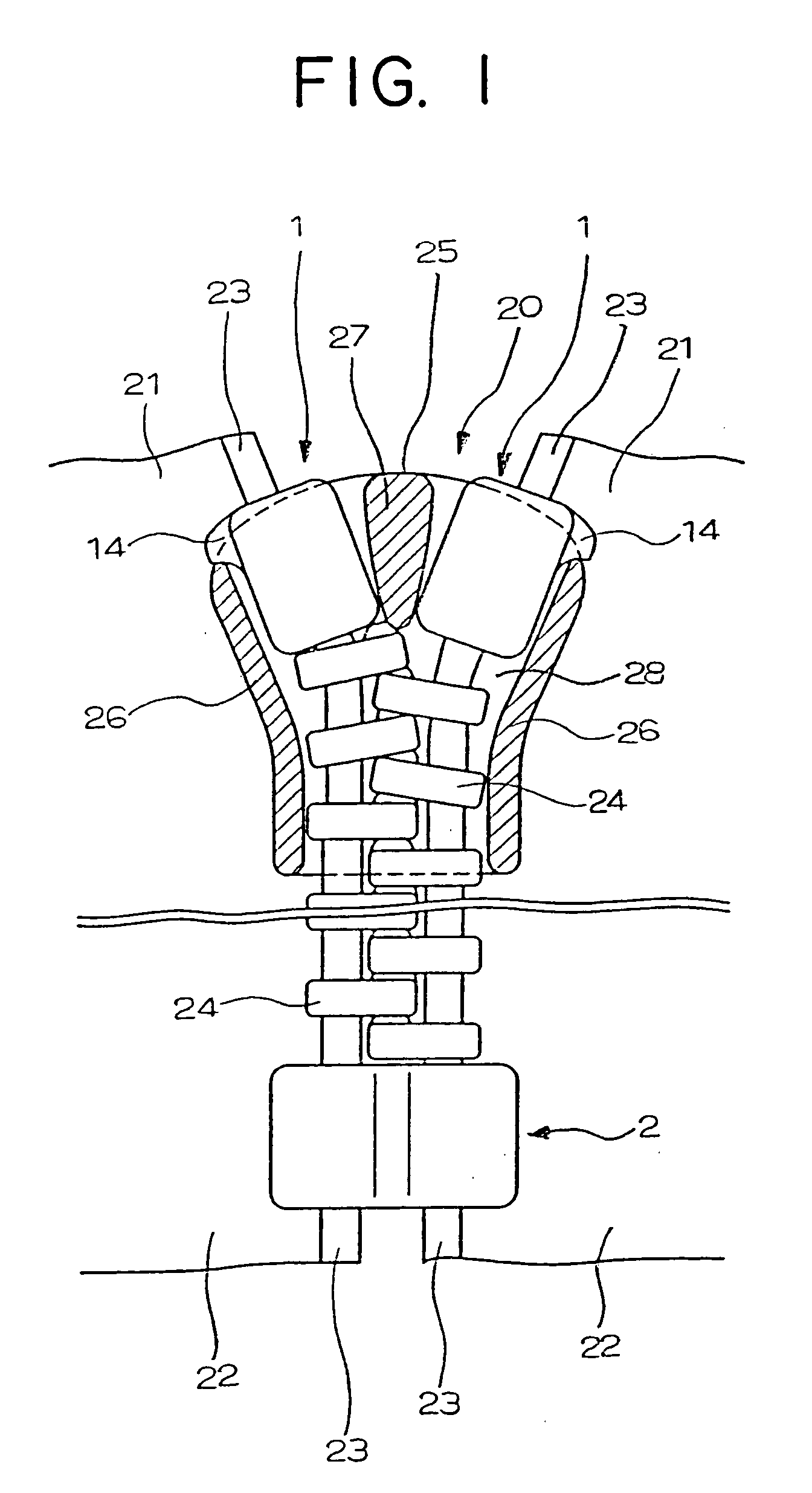
[0038]As shown in FIG. 1, the end stop for a slide fastener of the present invention concerns the top end stop 1 attached to the core portion 23 on each side edge of right and left fastener stringers 21 at the top end of a fastener chain 20 and the bottom end stop 2 mounted at the bottom end of the fastener chain 20 such that it crosslinks the right and left fastener stringers 21.

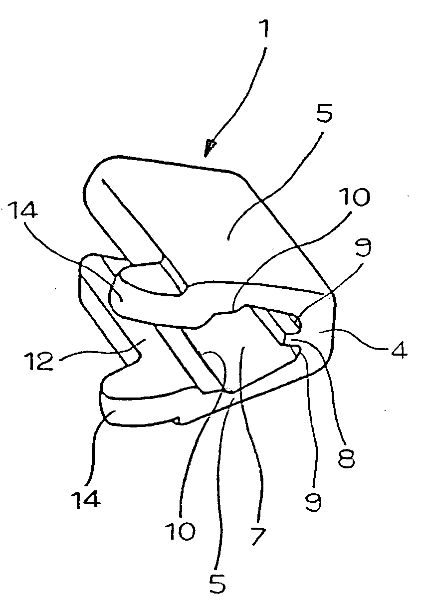
[0039]A end stop for a slide fastener according to a first embodiment of the invention shown in FIGS. 2 to 4 concerns the top end stop 1, and this top end stop 1 has a substantially U shaped section as shown in FIGS. 3 and 4 so that the opening portion at the front end thereof is slightly expanded, whereby the core portion 23 of the fastener tape 22 can be inserted. The top end stop 1 has the rectangular or rectangular piped base portion 4 which is flat at the central portion and the leg portions 5 each having a key-shaped section are extended in a bent manner from the upper and lower long sides of the base...

second embodiment

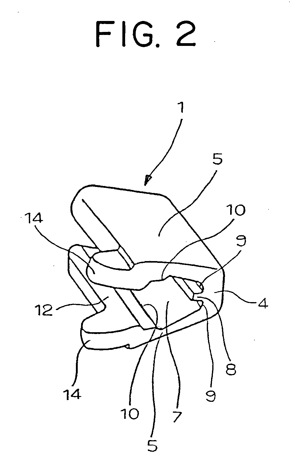
[0043]Next, an end stop for a slide fastener according to a second embodiment of the invention shown in FIGS. 5 to 7 concerns the top end stop 1. Although the top end stop of this type is substantially of the same configuration as the above-described first embodiment, it is different from the first embodiment in that no locking piece is provided at the front end of the leg portion 5 and the base portion 4 of the top end stop 1 is formed thicker, while the other structures are completely the same. A row of the projecting portion 8 is provided on the inner face of the base portion 4 of the top end stop 1, and further, the gap portion 9 is provided between the projecting portion 8 and the root of the leg portion 5. In addition, the accommodation portion 7 is provided such that it is surrounded by the base portion 4 and the leg portions 5, so that the core portion 23 of the fastener tape 22 disposed in the accommodation portion 7 is positioned accurately within the accommodation portion...

third embodiment

[0045]As regards a end stop for a slide fastener according to a third embodiment of the invention shown in FIG. 8, no locking piece is provided at the front end of the leg portion 5 of the top end stop 1, the base portion 4 of the top end stop 1 is formed thicker, so that when the slider 25 is slid, it comes into a sliding contact with both the guide post 27 and the flange 26 of the slider 25, thereby generating a friction resistance, and consequently, the top end stop 1 does not pass through the element guide groove 28, as shown in the second embodiment. In the top end stop 1 shown in FIG. 8, the base portion 4 is formed in the same thickness as that of the base portion 4 of the top end stop 1 of the first embodiment, and the projecting width of the hook shaped portion 12 at the front end of the leg portion 5 is formed larger. As a result, the hook shaped portion 12 projects sideways further than a side end of upper and lower leg portions of the fastener elements 24 and then, the f...


PUM


Abstract

This invention relates to a top end stop having a substantially U-shaped section and a bottom end stop having a substantially lateral-H shaped section. In each end stop, leg portions having key-shaped sections, i.e., a hook shaped portion is provided at front ends thereof, are extended in a bent manner from a rectangular base portion, so that an accommodation portion surrounded by the base portion and a pair of leg portions is provided for accommodating a core portion. A row of a projecting portion is formed continuously/intermittently on an inner face of the base portion and a gap portion is provided between the projecting portion and the root of each leg portion. The projecting portion positions the core portion accurately and holds it, and in crimping the leg portions, the core portion is compressed, and the gap portion is filled thereby, so that the core portion is secured firmly.

Description

BACKGROUND OF THE INVENTION[0001]1. Field of the Invention[0002]This present invention relates to an end stop for a slide fastener for stopping a sliding of a slider, namely, a top end stop or a bottom end stop made of metal, secured adjacent to fastener elements of a slide fastener employing a fastener tape provided with a core portion on a side edge thereof.[0003]2. Description of the Related Art[0004]According to a conventionally known slide fastener disclosed in U.S. Pat. No. 2,161,329, as shown in FIG. 15, a top end stop for a slide fastener secured on a swollen core portion 123 formed on a side edge of a fastener tape 122 is employed. In the top end stop, a metal plate is bent into a fallen U shape, projecting portions 108 are provided on each of front and rear ends of a central base portion such that the projecting portions 108 project inward and leg portions 105 are formed on both sides of the base portion while plural ribs (not shown) are provided protrudedly on an inner fa...

Claims


Application Information

Patent Timeline
Patent Type & Authority Applications(United States)
IPC IPC(8): A44B19/38A44B19/36
CPCA44B19/36Y10T24/2595Y10T24/2598
Inventor DETO, TATSUYA
Owner YKK CORP
Why Eureka
Try Eureka