Apparatus for determining pickup pose of robot arm with camera

a robot arm and camera technology, applied in the field of apparatus for determining the pickup pose of the robot arm, can solve the problem that the user cannot grasp the orientation of the workpiece with respect to the camera, and achieve the effect of easy capture of the workpi

Inactive Publication Date: 2009-09-17
DENSO WAVE INC
View PDF20 Cites 51 Cited by
  • Summary
  • Abstract
  • Description
  • Claims
  • Application Information

AI Technical Summary

Benefits of technology

[0031]In view of the background, an object of an aspect of the present invention is to provide apparatuses for determining a pickup pose of a robot with a camera; these apparatuses are designed to easily capture a workpiece within an FOV of the camera.

Problems solved by technology

First, the user may not grasp which orientation the workpiece is located in with respect to the camera because no images of the workpiece are displayed on the screen of the display device.

Method used


Image

  • Apparatus for determining pickup pose of robot arm with camera
  • Apparatus for determining pickup pose of robot arm with camera
  • Apparatus for determining pickup pose of robot arm with camera

Examples


Embodiment Construction

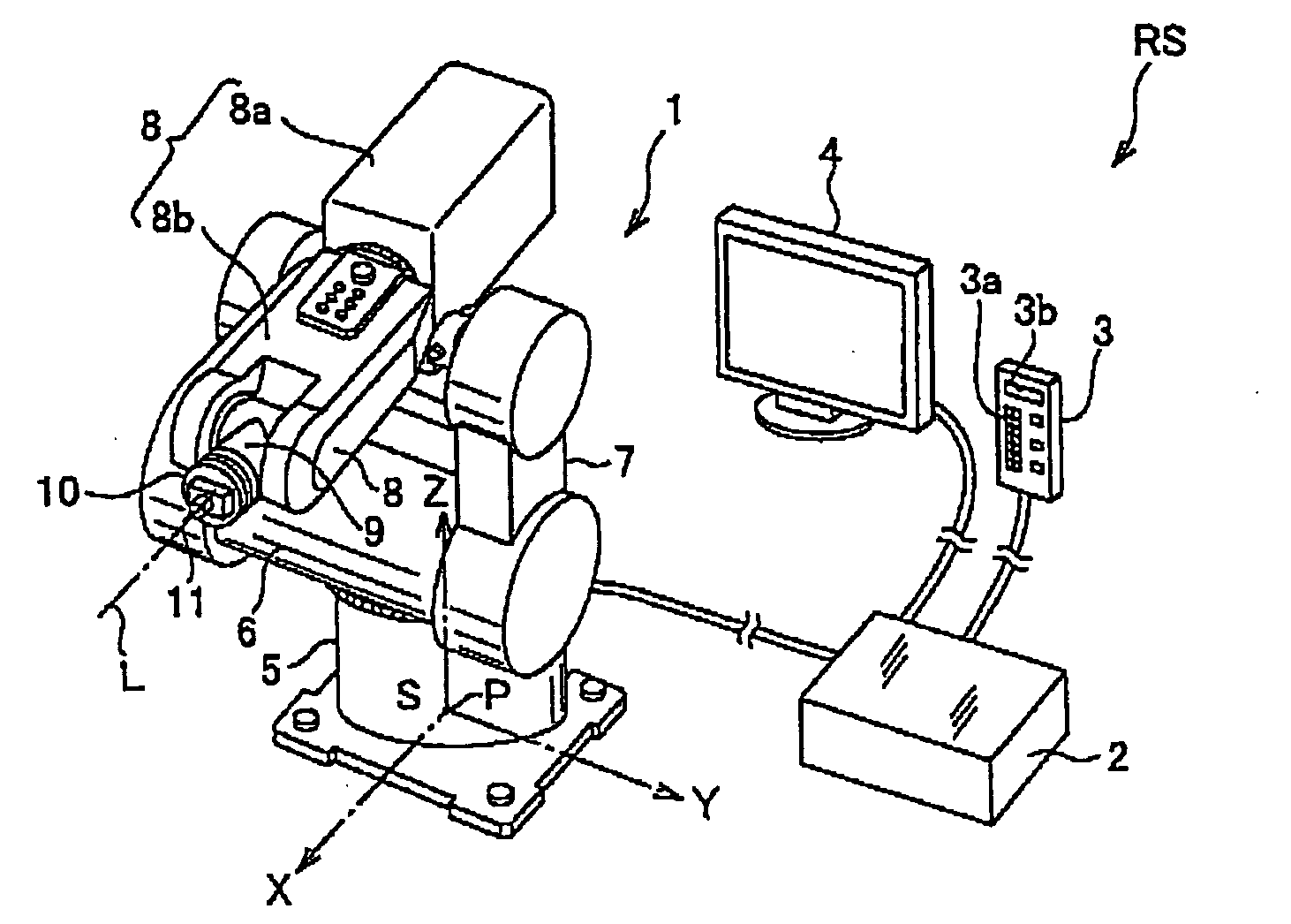
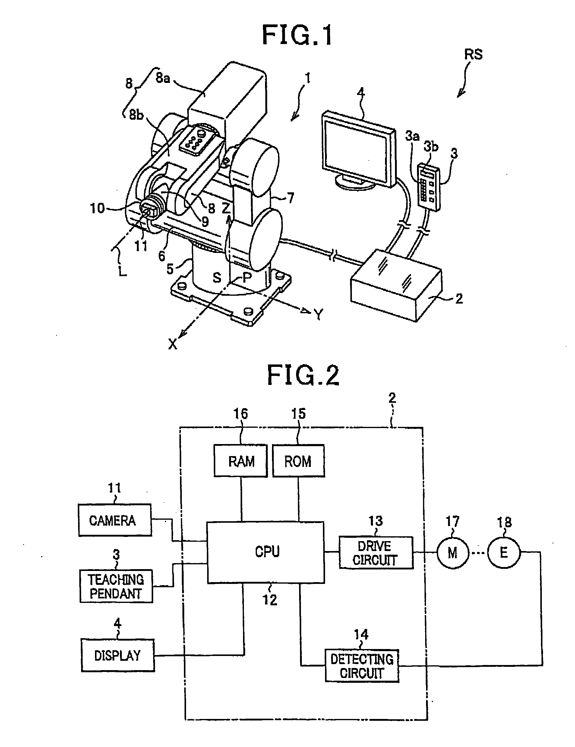
[0052]An embodiment of the present invention will be described hereinafter with reference to the FIGS. 1 to 15. In the embodiment, the present invention is applied to a robot system RS.

[0053]For example, the robot system RS is applied to a visual inspection apparatus for visually checking whether parts are properly mounted to their proper positions of assembled workpieces 19 during the final process of an assembly line of the workpieces 19.

[0054]Referring to FIG. 1, the robot system RS is preferably equipped with a robot body 1, a controller 2 electrically connected thereto via a cable and designed to control the robot body 1, a teaching pendant 3 electrically connected to the controller 2 via a cable, and a display 4 electrically connected to the controller 2 via a cable.

[0055]The teaching pendant 3 is equipped with a manually operable portion, such as a touch panel, 3a and a display, such as an LCD display, 3b. User's manual operations of the manually operable portion 3a allow var...


PUM


Abstract

In an apparatus, a coordinate obtaining unit drives a robot to move a camera opposing a workpiece in a first direction such that the workpiece is captured in an FOV of the camera. The coordinate obtaining unit obtains second and third coordinates of a preset point of the robot arm in respective second and third axes of a three-dimensional coordinate system with the workpiece being captured in the FOV. The first, second, and third coordinates are defined as coordinates of a temporally defined reference point of the workpiece in the three-dimensional coordinate system. A pose determining unit drives, at a given timing, the robot arm to determine a pose of the preset point based on a positional relationship between the first, second, and third coordinates of the temporally defined reference point of the workpiece and actual coordinates of the preset point of the robot arm.

Description

CROSS REFERENCE TO RELATED APPLICATIONS[0001]This application is based on Japanese Patent Application 2008-052671 filed on Mar. 12, 2008. This application claims the benefit of priority from the Japanese Patent Application, so that the descriptions of which are all incorporated herein by reference.FIELD OF THE INVENTION[0002]The present invention relates to apparatuses for determining a pickup pose of a robot arm with one end to which a camera is attached. The term “pickup pose” is designed to include at least one o a position of a predetermined point of the robot arm at which an image is to be picked up by the camera, and an orientation of a predetermined reference axis of the robot arm in which an image is to be picked up by the camera.BACKGROUND OF THE INVENTION[0003]Visual inspection apparatuses, as examples of inspection equipment for visually checking whether parts are properly assembled to their designed positions of workpieces, are designed to carry out such visual checking ...

Claims


Application Information

Patent Timeline
Patent Type & Authority Applications(United States)
IPC IPC(8): B25J9/02B25J19/04G05B15/00G06F19/00B25J9/22G05B19/19
CPCB25J9/1697B25J19/023G05B2219/37208G05B2219/37017G05B19/401
Inventor UEYAMA, TSUYOSHITAKAHASHI, MINORU
Owner DENSO WAVE INC
Why Eureka
Try Eureka