Adjustable blood filtration device

a filter device and adjustable technology, applied in the field of blood filter, can solve the problems of preventing the device from effectively capturing additional material, clogging the blood filter, and affecting the flow of blood through the filter, so as to minimize the likelihood of the blood filter becoming blocked and ineffective during use, and effectively capture embolic material.

Inactive Publication Date: 2006-03-21
EDWARDS LIFESCIENCES CORP
View PDF27 Cites 56 Cited by
  • Summary
  • Abstract
  • Description
  • Claims
  • Application Information

AI Technical Summary

Benefits of technology

[0010]When a cannula is used, it has a distal end adapted to enter an artery, a proximal end adapted to receive blood from a bypass oxygenator machine, and a lumen that extends from the proximal end to the distal end. The cannula can be a hybrid of extruded, drawn or welded metal tubing and molded or machined plastics, or could be made entirely of metal or of plastic. The cannula also includes a port for receiving the modular filter apparatus. The port may be attached to or integrally formed on the outer surface of the cannula, the inner surface of the cannula, such as a lumen parallel with the main cannula lumen, possibly on the front (downstream area), back (upstream area) or side of the cannula. Preferably, a side port is located adjacent the distal end of the cannula, for example above a suture flange thereon. More preferably, the side port extends diagonally from the outer surface to facilitate directing the filter device towards the distal end of the cannula. A passage extends from the side port to the lumen in the cannula, or alternatively, may extend distally from the side port along a wall of the cannula to an outlet on or adjacent the distal end of the cannula. The side port may include a hemostatic valve across the passage to provide a fluid-tight seal, yet allow a modular filter cartridge to be received in and removed from the side port. The cannula may also include a cannula liner to prevent the escape of blood from the outlet.
[0018]The ability to replace the filter at any time during a procedure is particularly useful in cardiac surgery. For example, a cannula and filter may be deployed as described above within the aorta. The aorta may then be clamped in preparation for a bypass procedure, possibly dislodging embolic material from the wall of the aorta and traveling downstream. With the filter deployed, however, embolic material released during this action may easily be captured by the filter device. Once the aorta is clamped, the risk of embolic material breaking loose is substantially reduced, and so the filter may be removed without substantial concern about embolic material escaping to other areas of the patient.
[0019]Later in the surgery, a new filter may be introduced into the aorta when the risk of embolic material becoming dislodged is again increased, as for example when the aorta is unclamped. Because a new filter may be deployed, any embolic material that is dislodged has a much greater likelihood of being captured by the filter without substantially impairing blood flow through the vessel. Thus, a cannula with modular filter apparatus may more effectively capture and remove embolic material released during extended procedures, such as coronary bypass surgery.
[0022]It is also useful to reduce trauma to the vessel that can be caused by a hollow vessel insertion device and thus an expandable obturator is also described. One embodiment of an obturator includes an obturator shaft that has a tapered distal end, a distal region and an outer surface and a plurality of spaced collet segments arranged coaxially around the distal region of the obturator shaft. Each segment is expandable between a contracted condition and an expanded condition and each segment has an inner surface that conforms to the outer surface of the obturator shaft and a proximal end coupled to the distal region of the shaft. The segment also includes an outwardly flaring elongated member that is expandable away from the outer surface of the obturator shaft. This elongated member forms a collet head at the distal end of the collet segment. The collet head has a proximal end that gradually thickens from the elongated member thereby forming a recess in the region where the elongated member is associated with the collet head. The distal end of the collet head is tapered to a thickness less than the proximal end of the head. This configuration allows the distal end of the insertion device to rest in the recess behind the collet head, and the overall profile of the collet head and distal end of the shaft is smoothly tapered to advance the entering insertion device.
[0024]Accordingly, a principal object of the present invention is to provide a modular adjustable blood filter apparatus and delivery system that allows the filter to be decoupled from the delivery system when not needed, and that allows a new filter to be introduced to more effectively capture embolic material within the vessel, such as during an extended surgical procedure.
[0025]It is also an object of the present invention to provide an insertion device with modular filter apparatus that substantially minimizes the likelihood of the blood filter becoming clogged and ineffective during use.

Problems solved by technology

Such embolic material may travel downstream, possibly becoming lodged in another portion of the blood vessel or possibly reaching a vital organ, such as the brain, where the material can cause substantial injury to the patient.
The use of a cannula with such a filter device, however, may not be as effective as desired.
Because of the length of time of most cardiac procedures, the filter mesh may eventually become clogged due to thrombus formation or buildup of embolic material, preventing the device from effectively capturing additional material and / or possibly impairing blood flow through the filter.

Method used


Image

  • Adjustable blood filtration device
  • Adjustable blood filtration device
  • Adjustable blood filtration device

Examples


Embodiment Construction

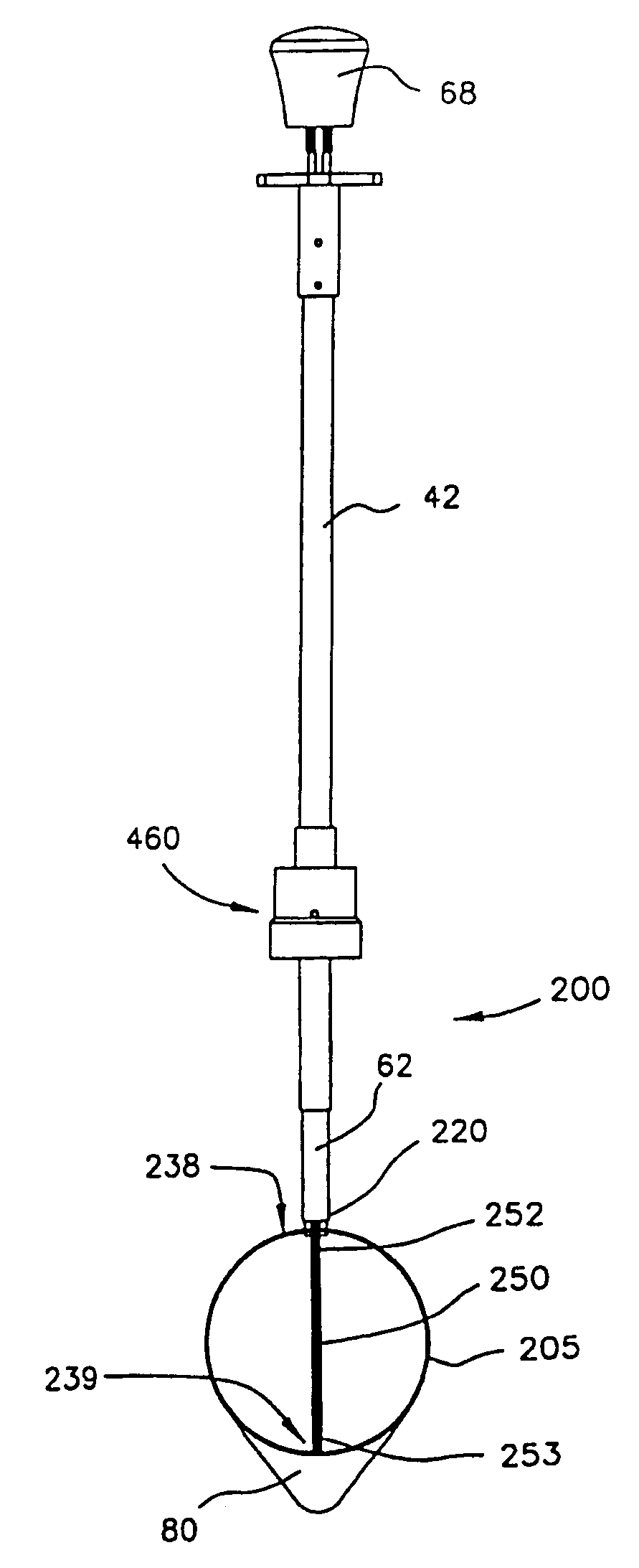
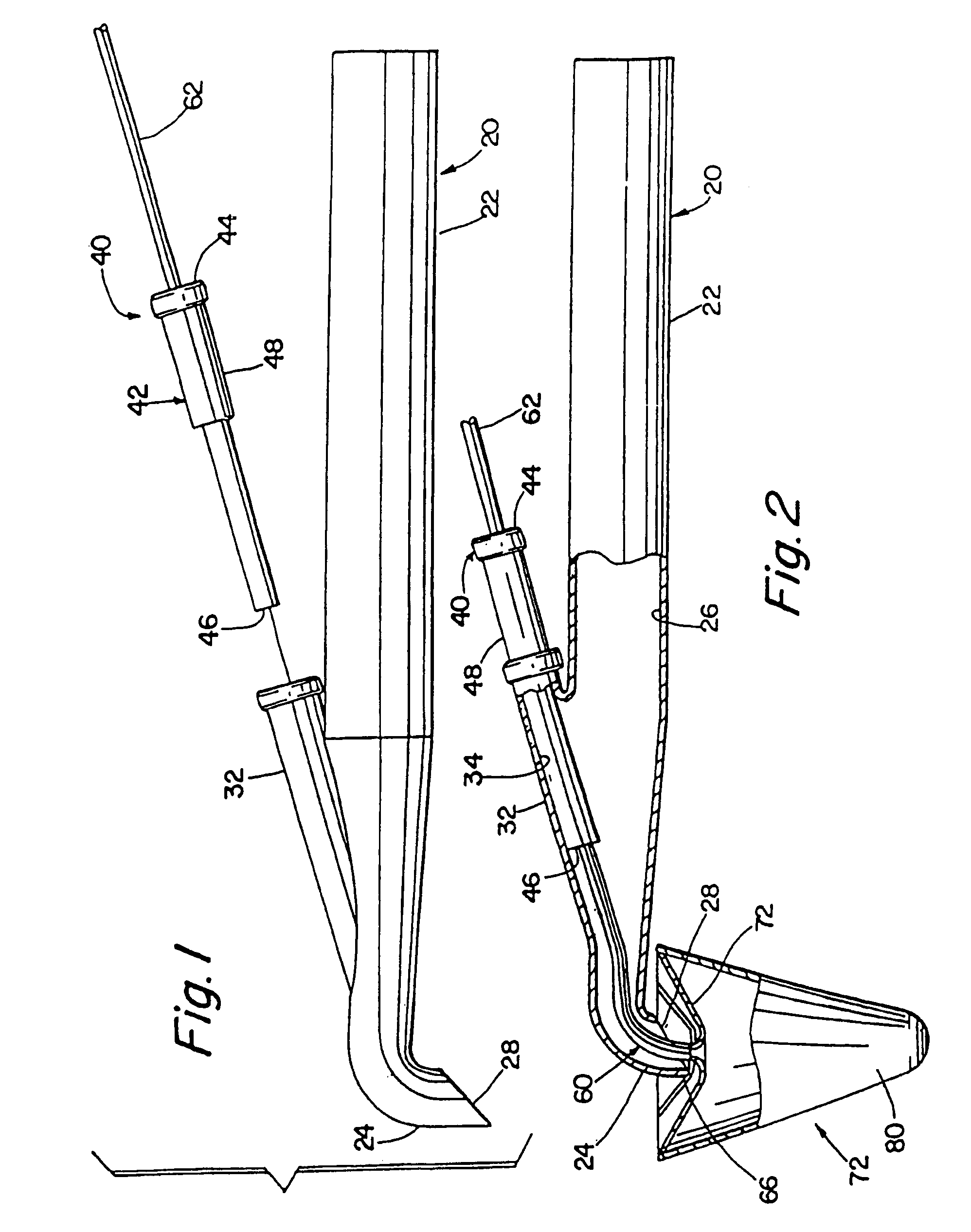
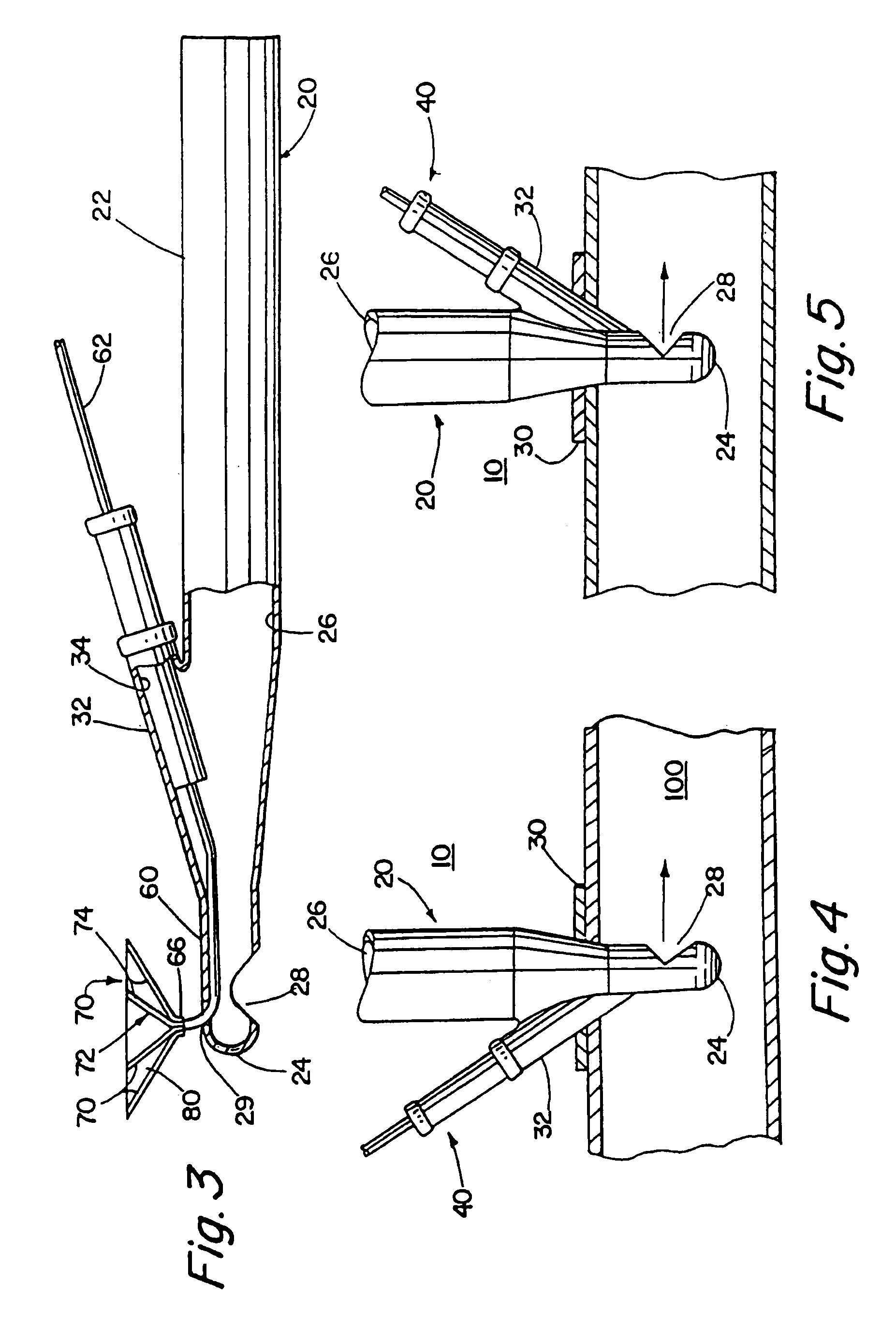
[0105]Turning now to the drawings, FIGS. 1–5 and 16–19 show embodiments of an arterial cannula with modular filter device 10. As shown in FIGS. 18 and 19, the device 10 generally includes three components, namely a cannula 20, a tubular cartridge 42 and an expandable filter device 60. In certain embodiments, the latter two components together defining a modular filter apparatus 40.

[0106]The cannula 20 is an elongate tubular member 22, having a proximal end (not shown), a distal end 24, and a lumen 26 that extends between the proximal and distal ends 24. The proximal end is adapted for receiving blood from a bypass-oxygenator machine (not shown). The distal end 24 has a tapered, curved and / or rounded end adapted to enter an artery (not shown), and includes an outlet 28 communicating with the lumen 26. The cannula 20 may be formed from a substantially rigid material.

[0107]The cannula 20 includes a side port 32 for receiving the modular filter apparatus 40. The side port 32 may be atta...


PUM


Abstract

A medical device comprising a tubular member having a proximal end, a distal end, and a lumen extending therebetween. An adjustable filter is provided having a frame and a mesh disposed about the frame. The frame is generally circular when deployed and has a first point, a first arc extending 180° from the first point to a second point on the circular frame that is opposite the first point, and a second arc extending 180° from the first point to the second point. The filter is deployed by advancing the frame distally through the tubular member with the second point leading and the first point trailing.

Description

[0001]This is a divisional of U.S. application Ser. No. 10 / 001,465, filed Oct. 31, 2001, now U.S. Pat. No. 6,656,204 which is a continuation of U.S. application Ser. No. 09 / 630,805, filed Aug. 2, 2000, now U.S. Pat. No. 6,319,268 which is a continuation of U.S. application Ser. No. 09 / 392,059, filed Sep. 8, 1999, now U.S. Pat. No. 6,152,947, which is a continuation of U.S. application Ser. No. 09 / 070,660, filed Apr. 29, 1998, now U.S. Pat. No. 6,007,557, the contents of which are expressly incorporated herein by reference in their entirety.FIELD OF THE INVENTION[0002]The present invention relates generally to blood filter and associated devices for temporary placement in a blood vessel to capture embolic material, and more particularly to a hollow vessel insertion device with an adjustable filter apparatus for placement in a blood vessel to carry blood to the vessel and to entrap embolic material in the vessel, for example when delivering blood to the aorta from a bypass-oxygenator ...

Claims


Application Information

Patent Timeline
Patent Type & Authority Patents(United States)
IPC IPC(8): A61M29/00A61B17/00A61B19/00A61F2/01
CPCA61B19/46A61F2/01A61F2/013A61F2002/011A61F2230/008A61F2230/0006A61F2230/0067A61F2230/0071A61F2230/0076A61F2002/018A61B90/06A61F2/0105A61F2/0108A61F2/011A61F2/012
Inventor AMBRISCO, WILLIAM M.MURPHY, RICHARD O.WOOD, TIMOTHY J.TUROVSKIY, ROMANMAAHS, TRACY D.ADDIS, BRUCE S.
Owner EDWARDS LIFESCIENCES CORP
Why Eureka
Try Eureka