Occipital Plate for Spinal Fusion

a technology of occipital plate and spinal cord, which is applied in the field of occipital plate for spinal cord fusion, can solve the problems of fatigue of rod material, long screws and large coupling assemblies that cannot be mounted directly to the skull without undue risk, and many coupling assemblies that would prove extremely and unduly cumbersome, etc., and achieves convenient capture of spinal rods, further adjustment of positioning, and further adjustment of device

Active Publication Date: 2011-08-04
PIONEER SURGICAL TECH INC
View PDF15 Cites 57 Cited by
  • Summary
  • Abstract
  • Description
  • Claims
  • Application Information

AI Technical Summary

Benefits of technology

[0020]In another aspect of the invention, a plate member may include a track portion having guide tracks in which a pair of yoke members are slidably disposed. The sliding of the yoke members along the guide tracks allows the distance between the yoke members to be adjusted so that the yoke members may capture spinal rods adjusted to various distances from one another. In addition, the yokes may be rotatably and / or pivotably coupled to the guide tracks in a polyaxial manner that allows for rotation and / or pivoting in one or more planes in order to easily capture spinal rods so that they extend in a variety of different directions relative to the plate member, and specifically the track portion thereof. For instance, the yoke may be provided with a swiveling neck portion that is slidably received in the track member and allows the yoke member to swivel in one or more directions with respect to the track member.
[0021]In one preferred form, the yoke member may rotate about an axis of the neck portion so that a rod receiving channel or opening in the yoke may be positioned to face in various different directions with respect to the direction in which the yoke slides along the track member. In another preferred aspect of the invention, the neck member forms a ball-and-socket connection with the yoke member in order to allow pivoting of the yoke member in at least two planes in addition to rotation about an axis of the neck portion. Locking members may be provided in order to secure the spinal rods to the yoke members and to fix the position of the yoke members with respect to the track member and plate member. In one aspect of the invention, a single locking member associated with each yoke member fixes the position of a spinal rod with respect to the yoke member and fixes the pivoted and rotated position of the yoke member with respect to the neck portion and / or track member. In another aspect, a single locking member secures the position of two yoke members along the track member, such as by adjusting a clamp member that spans the length of the track member to exert frictional forces that prevent the yoke members from sliding relative to the track member. Alternatively, separate clamping members may be provided to prevent the sliding of each of the yoke members.
[0022]In another aspect of the invention, the rod receiving members may be coupled to the plate member by telescoping members that allow the distance of the rod receiving members from the plate member to be adjusted. This may include, for instance, a sleeve portion having an axial bore coupled to the plate member and a post member coupled to the rod receiving member, with the post member slidably received in the axial bore of the sleeve portion. Alternatively, the sleeve portion may be coupled to the rod receiving member and the post coupled to the plate member. The sleeve and post members also may be pivotably coupled to the plate member and / or rod receiving member in order to provide further adjustability to the positioning and orientation of the rod receiving members.
[0023]In another form, one or more rod receiving members may be coupled to a plate member by two or more ball-and-socket connections. A housing may be provided to connect one ball-and-socket connection to the next. In one preferred form, a single locking member is associated with each housing and is configured to lock the position of both ball-and-socket connections with respect to the housing. The ball-and-socket connections also may be pivotably and / or slidably connected to the plate member and / or the rod receiving member to provide further adjustability to the device.
[0024]The anchors used to secure the plate to the patient's skull may be expandable in order to increase their holding strength. For instance, the shank of the screw may be hollow and have one or more slits therein running parallel to the axis of the shank so that insertion of a pin or other member into the hollow shank causes the exterior of the shank to splay, expanding the width of the shank and applying additional lateral force against the bone adjacent to the shank exterior. This lateral force increases the load that may be placed on the screw in an axial direction before the screw is stripped out of the bone.

Problems solved by technology

When spinal rods are mounted to the skull, however, long screws and large coupling assemblies cannot be mounted directly to the skull without undue risk of penetrating the brain encased therein.
Many coupling assemblies also would prove extremely and unduly cumbersome if mounted directly to the skull, and may even protrude significantly from the back of the head.
This bending of the rod can fatigue the rod material, and also makes it difficult to reposition the elements of the stabilization system.
Even attempts to provide occipital plate devices with adjustability in order to accommodate spinal rods of various orientations still generally require significant manipulation and bending of spinal rods before they can be secured to the plate structure.
While the bolt may be rotated to adjust the direction of the rod or cable, this adjustment affects only one plane, and does not allow for adjustment of the angle of the rod or cable with respect to the surface of the plate.
However, the device does not allow multiple types of movement to provide a highly articulated device.
Furthermore, the coupling heads are relatively bulky and still hold the spinal rods relatively parallel to the plate surface.

Method used


Image

  • Occipital Plate for Spinal Fusion
  • Occipital Plate for Spinal Fusion
  • Occipital Plate for Spinal Fusion

Examples


Embodiment Construction

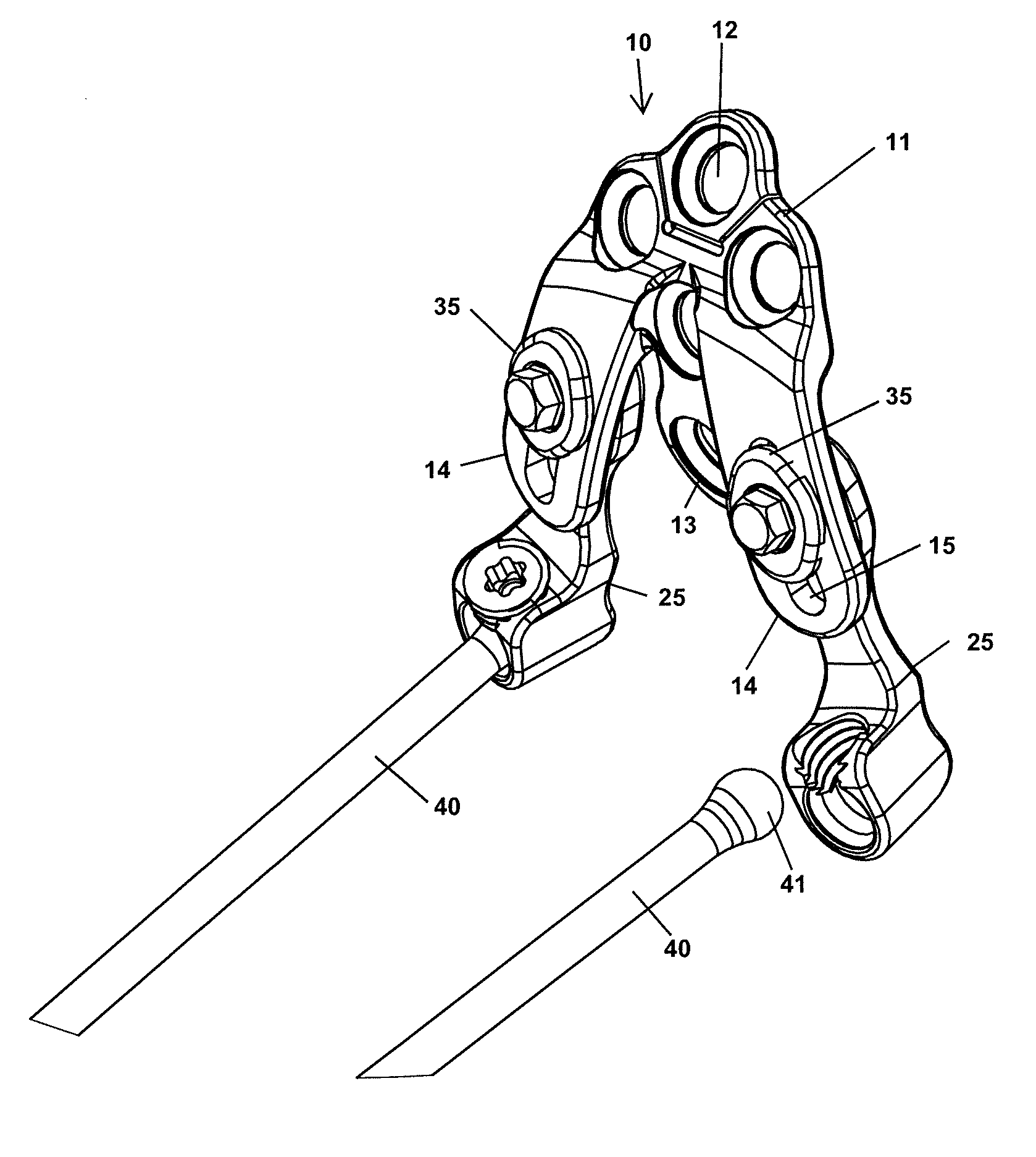
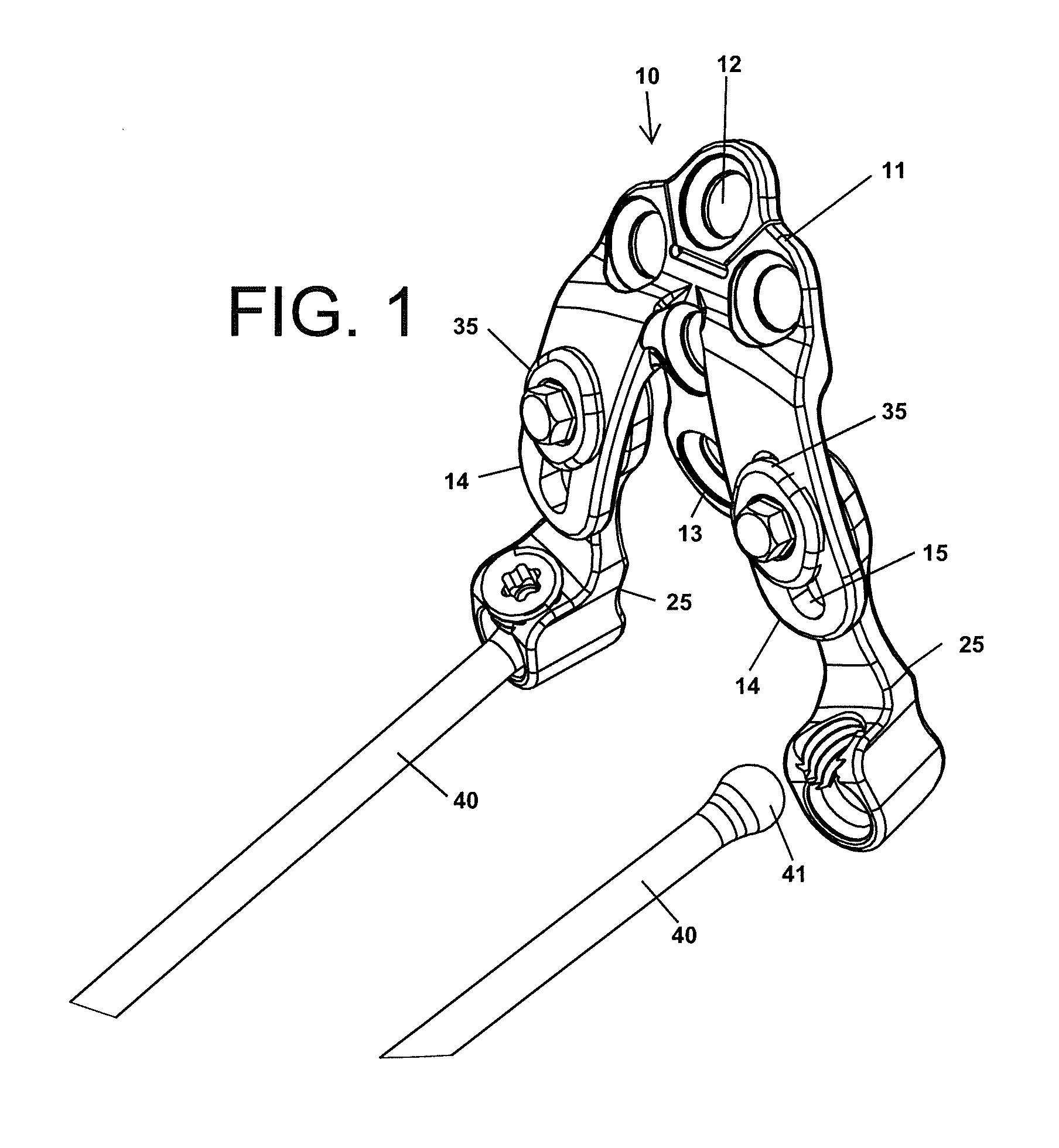
[0073]The novel plate devices disclosed herein are better designed to receive and hold spinal rod members than prior art plate devices configured for mounting to the occipital region of the skull. For instance, to illustrate the contrast between the presently disclosed occipital plate devices and the prior art, a prior art device that requires spinal rods to be bent substantially to be received by the plate device attached to the skull is shown in FIG. 1. A clamping device 3 on each side of the plate 2 secures an end of a spinal rod 5 parallel to the plate surface. The clamping device may include a threaded set screw that clamps against the spinal rod, a bracket that is secured against the rod, or the like. A series of pedicle screws 7 secure the rods 5 to the vertebrae. Since the plate 2 and clamp devices 3 are mounted transverse to the axis of the spine, the spinal rods 5 must be bent outward away from the spine in order to connect to the plate 2.

[0074]The plate devices provided h...


PUM


Abstract

Plate devices are provided for mounting to bone and receiving one or more spinal rods. The devices may include coupling members or rod receiving members coupled to the plate member and configured to have multiple degrees of adjustability in order to accommodate elongate connecting members of various orientations. The plate devices may also include quick locking features or locking devices that secure multiple points of articulation simultaneously.

Description

CROSS-REFERENCE TO RELATED APPLICATION[0001]This application claims benefit of U.S. Provisional Application 61 / 298,488, filed Jan. 26, 2010, which is hereby incorporated herein by reference in its entirety.FIELD OF THE INVENTION[0002]The invention relates generally to devices for securing the ends of spinal rods or other elongate fixation members to the skull of a patient for spinal repair and / or fusion surgeries.BACKGROUND OF THE INVENTION[0003]Rigid or semi-rigid elongate members, such as spinal rods, may be mounted to the spinal column in order to stabilize or immobilize vertebrae of the spinal column for a variety of purposes. For instance, spinal rods are often secured to adjacent vertebral bodies via anchor members in order to promote fusion of the two vertebrae as a treatment for degenerative disc disease, spondylolisthesis, spinal stenosis, fractures of the vertebrae, and other conditions. Limiting or preventing motion of the vertebrae promotes the healing process. By remova...

Claims


Application Information

Patent Timeline
Patent Type & Authority Applications(United States)
IPC IPC(8): A61B17/70
CPCA61B17/70A61B17/7032A61B17/7037A61B17/7041A61B17/7002A61B17/7055A61B17/7059
Inventor GEPHART, MATTHEW P.BERMAN, PHILLIP J.
Owner PIONEER SURGICAL TECH INC
Why Eureka
Try Eureka