Liquid application apparatus, liquid application method, inkjet recording apparatus and inkjet recording method

a liquid application apparatus and liquid application technology, applied in the direction of coatings, pretreated surfaces, printing, etc., can solve the problems of reducing difficult maintenance, and non-uniform steps on the application surface of the base member, so as to prevent the decline in the performance of scraping off excess application liquid and improve the image quality. , the effect of reducing the frequency of blade replacemen

Inactive Publication Date: 2009-07-02
FUJIFILM CORP
View PDF6 Cites 59 Cited by
  • Summary
  • Abstract
  • Description
  • Claims
  • Application Information

AI Technical Summary

Benefits of technology

[0030]This aspect of the invention is suitable for an inkjet recording method of a so-called transfer type in which an ink image is formed by causing two liquids, namely, an ink and a treatment liquid, to react on an intermediate transfer body, and the ink image is then transferred to a recording medium. It is possible to apply a treatment liquid as a film of uniform thickness on the intermediate transfer body, and therefore it is possible to improve the image quality.
[0031]According to the present invention, even if the blade suffers wear during use, since the blade holding body is biased continuously by the plurality of biasing devices disposed in the axial direction of the coating

Problems solved by technology

However, in the case of a liquid application apparatus of this kind, when the front tip of a blade is placed in contact with the surface of a gravure roller and the applied liquid which has been deposited in excess on the surface of the gravure roller is thereby scraped off, there is a problem in that vibration of the blade occurs due to the contact between the blade and the gravure roller, and hence application defects such as step-shaped non-uniformities occur on the application surface of the base member onto which the application liquid is applied.
Nevertheless, in the invention described in Japanese Patent Application Publication No. 2006-255611, the blade which is fixed indirectly to the blade holder is caused to make contact with the gravure roller by three apparatuses, namely, an elevat

Method used


Image

  • Liquid application apparatus, liquid application method, inkjet recording apparatus and inkjet recording method
  • Liquid application apparatus, liquid application method, inkjet recording apparatus and inkjet recording method
  • Liquid application apparatus, liquid application method, inkjet recording apparatus and inkjet recording method

Examples


first embodiment

General Composition of Inkjet Recording Apparatus Relating to First Embodiment of the Present Invention

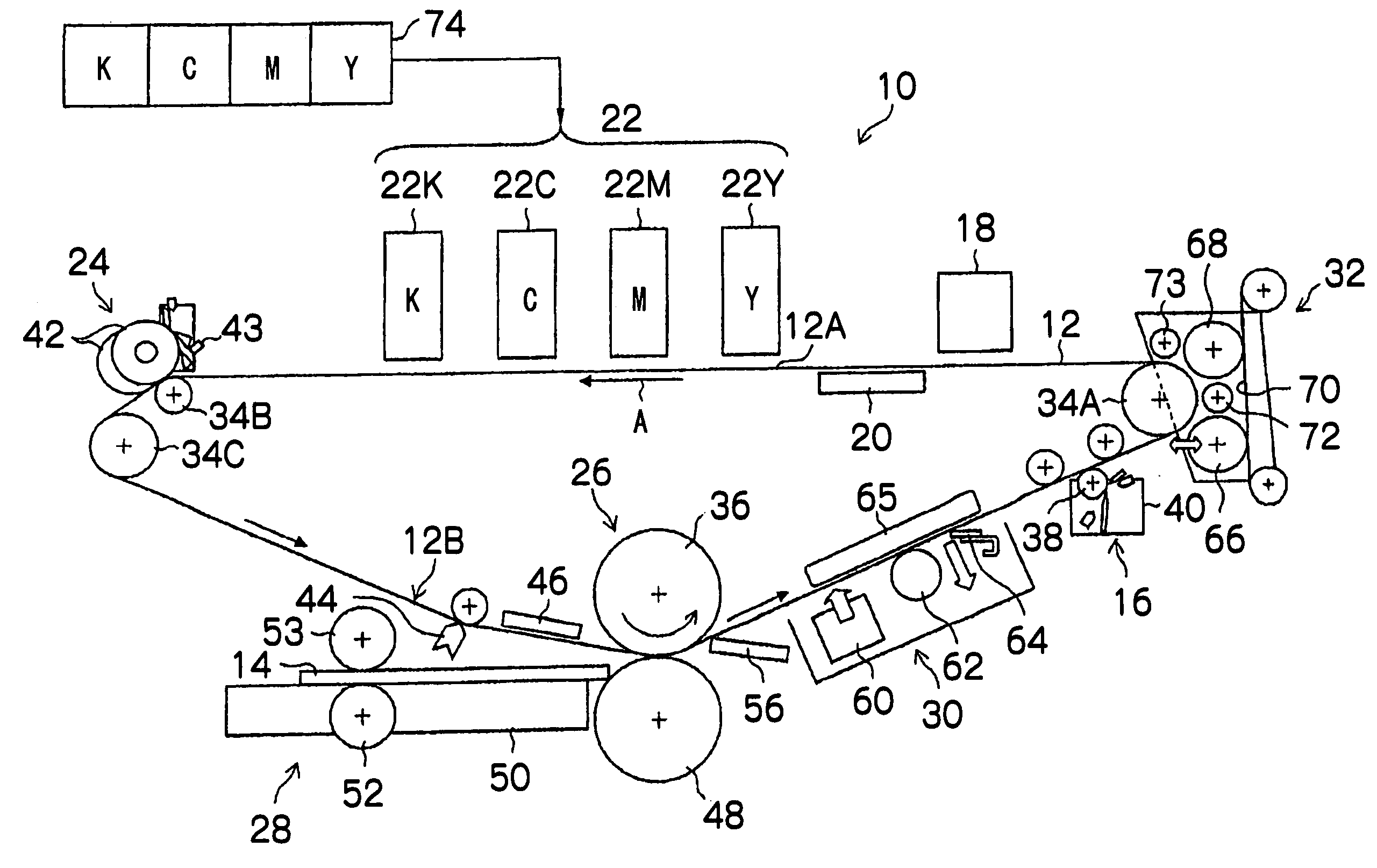
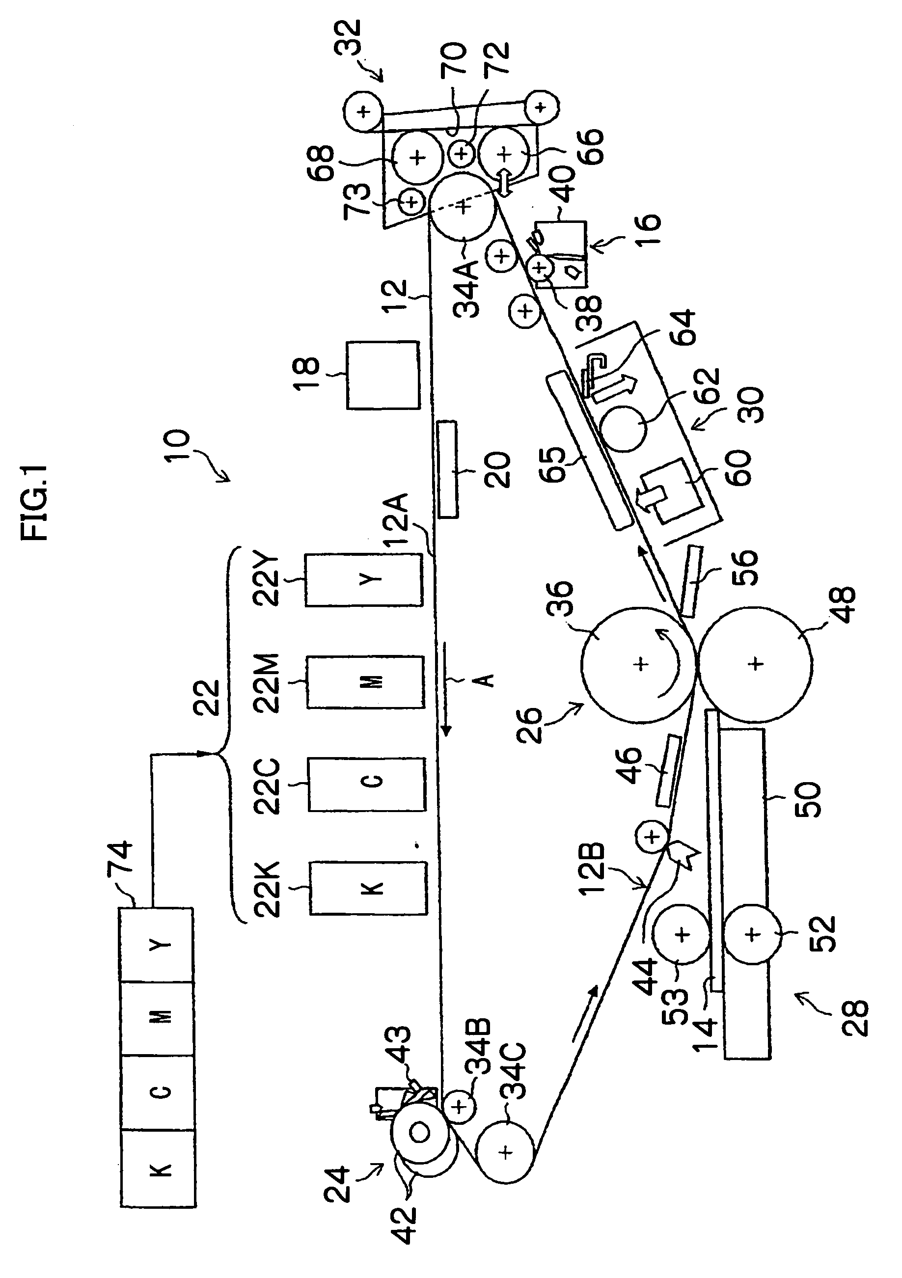
[0049]FIG. 1 is a diagram of the general composition of an inkjet recording apparatus relating to a first embodiment of the present invention.

[0050]As shown in FIG. 1, the inkjet recording apparatus 10 according to the present embodiment is a recording apparatus which employs a transfer method in which an image (primary image) is recorded onto an intermediate transfer body 12 (base member) which is a non-permeable medium, and is then transferred to a recording medium 14 such as normal paper, to form a main image (secondary image).

[0051]The inkjet recording apparatus 10 principally comprises a treatment liquid application unit 16 (corresponding to a portion where the “liquid application apparatus” according to the present invention is applied) which applies an aggregating treatment liquid (hereinafter, also simply called a “treatment liquid” in the present embodiment) to the interme...

example 1

Treatment Liquid Example 1

[0114]A treatment liquid (Example 1) was prepared according to the composition shown in Table 1. Thereupon, the physical properties of the treatment liquid (Example 1) thus obtained were measured, and the pH was 3.6, the surface tension was 28.0 mN / m, and the viscosity was 3.1 mPa·s.

TABLE 1MaterialWeight %2-pyrrolidone-5-carboxylic acid10(made by Tokyo Chemical Industry Co., Ltd.)Lithium hydroxide - hydride (made by Wako Pure Chemical2Industries, Ltd.)Olfine E1010 (made by Nissin Chemical Industry Co., Ltd.)1Ion-exchanged water (Deionized water)87

example 2

Treatment Liquid Example 2

[0115]A treatment liquid containing added surfactant having the composition shown in Table 2 was prepared (Example 2). Thereupon, the physical properties of the treatment liquid (Example 2) thus obtained were measured, and the pH was 3.5, the surface tension was 18.0 mN / m, and the viscosity was 10.1 mPa·s.

TABLE 2MaterialWeight %2-pyrrolidone-5-carboxylic acid10(made by Tokyo Chemical Industry Co., Ltd.)Lithium hydroxide - hydride (made by Wako Pure Chemical2Industries, Ltd.)Olfine E1010 (made by Nissin Chemical Industry Co., Ltd.)1Fluorine surfactant 13Ion-exchanged water84

[0116]The chemical formula of the fluorine surfactant 1 used in Table 2 is shown as follows.

Preparation of Ink

[0117]An example of the preparation of an ink used in the present embodiment is described below.

Preparation of (Polymer Dispersion) Cyan Ink

[0118]A solution comprising 6 parts by weight of styrene, 11 parts by weight of stearyl methacrylate, 4 parts by weight of styrene macromer A...


PUM


Abstract

A liquid application apparatus has: a rotatable coating cylinder which has a circumferential surface onto which an application liquid is supplied; a base member which is conveyed continuously while making contact with the rotatable coating cylinder; a blade which scrapes off excess liquid of the application liquid in such a manner that a prescribed amount of the application liquid remains on the rotatable coating cylinder, before the rotatable coating cylinder transfers, onto the base member, the application liquid; a blade holding body which holds the blade, is supported on a supporting shaft and is rotatable in a rotation direction; and a plurality of biasing devices which are disposed in an axial direction of the rotatable coating cylinder and bias the blade holding body in the rotation direction of the blade holding body in such a manner that the blade makes contact with the circumferential surface of the rotatable coating cylinder.

Description

BACKGROUND OF THE INVENTION[0001]1. Field of the Invention[0002]The present invention relates to a liquid application apparatus, a liquid application method, an inkjet recording apparatus and an inkjet recording method, and more particularly, to technology whereby liquid that has been deposited in excess onto the surface of a coating cylinder as in gravure roller application, is scraped off to a prescribed application amount by a blade and the liquid is then applied to a base member.[0003]2. Description of the Related Art[0004]An inkjet recording method performs recording by ejecting droplets of ink respectively from a plurality of ejection nozzles which are formed in an inkjet head, and this type of method is used widely since it enables images of high quality to be recorded onto recording media of a wide variety of types, while incurring low running costs and producing little noise during the recording operation.[0005]Furthermore, an inkjet recording method is also known which is ...

Claims


Application Information

Patent Timeline
IPC IPC(8): B05C1/08B44C1/16
CPCB41J2/0057B41J2202/21B41J2202/20B41J2002/14459
Inventor INOUE, SEIICHIYOSHIDA, JUNICHI
Owner FUJIFILM CORP
Why Eureka
Try Eureka