Supercharge Your Innovation With Domain-Expert AI Agents!

Lamp control circuit and method of driving a lamp

a technology of control circuit and lamp, which is applied in the direction of electric variable regulation, process and machine control, instruments, etc., can solve the problems of difficult to change the lamp setting, difficult to supply new settings to the lamp driving circuit, and complicated installation process, etc., and achieve the effect of simple and logistical installation process

Active Publication Date: 2009-07-02
SIGNIFY HLDG BV
View PDF11 Cites 14 Cited by
  • Summary
  • Abstract
  • Description
  • Claims
  • Application Information

AI Technical Summary

Benefits of technology

The present invention provides a method for controlling a lamp using a lamp control circuit. The circuit has a communication circuit and a lamp driving circuit. The method involves storing a lamp operating parameter in a memory of the communication circuit and supplying power to the lamp driving circuit to drive the lamp accordingly. The communication circuit can communicate wirelessly with an external device, such as a RFID transponder, to receive and store the lamp operating parameter. The system also includes an external control device for communicating the lamp operating parameter to the communication circuit. The technical effects of this invention include improved control over lamps, simplified installation and maintenance, and reduced costs.

Problems solved by technology

Thus, a logistically complex installation process has to be performed for installing the e.g. road lighting systems.
After installation, in particular in road lighting applications, it is difficult to change the lamp settings, since safety regulations require that a supply voltage is disconnected from the lamp, when a housing of the lamp is opened.
Consequently, it is difficult to supply new settings to a lamp driving circuit, since the lamp driving circuit is not powered.

Method used


Image

  • Lamp control circuit and method of driving a lamp
  • Lamp control circuit and method of driving a lamp
  • Lamp control circuit and method of driving a lamp

Examples


Embodiment Construction

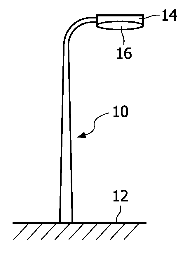
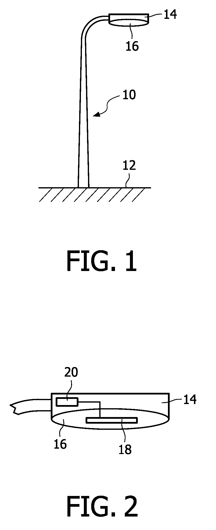
[0019]FIG. 1 shows a light pole 10 for illuminating a road 12. The light pole 10 is provided with a lamp housing 14 comprising a transparent housing compartment 16 for holding a lamp.

[0020]FIG. 2 shows the lamp housing 14 in more detail. The lamp housing 14 encases a lamp control circuit 20. A lamp 18 is positioned in the transparent housing compartment 16 and connected to the lamp control circuit 20 for receiving power. The lamp control circuit 20 is connected to a power supply (not shown), when the lamp housing 14 is in a closed state. When the lamp housing 14 is opened, for example for maintenance and / or replacing the lamp 18, the lamp control circuit 20 may be automatically disconnected from the power supply for safety reasons.

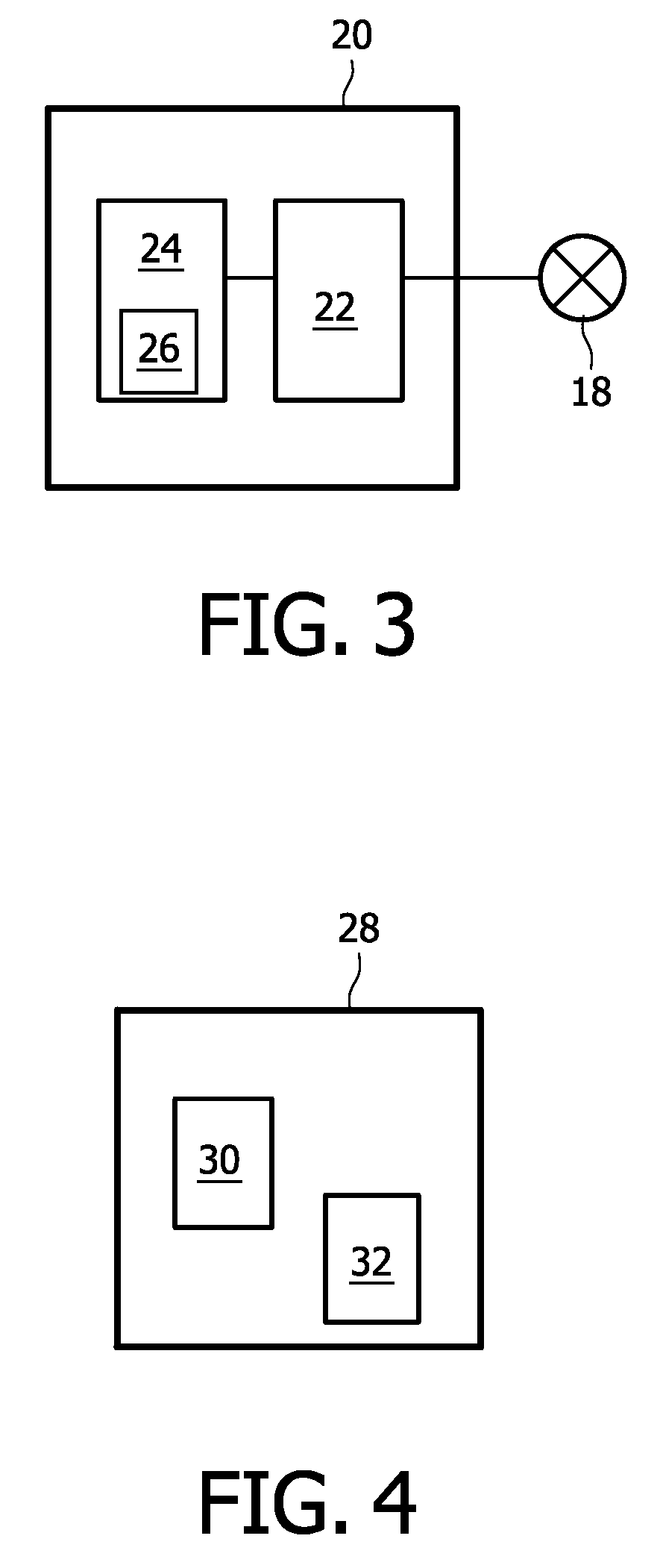
[0021]The lamp control circuit 20 is configured to control the light output of the lamp 18. Whereas the lamp 18 was configured to be on or off in the past, nowadays the lamp 18 may be controlled to output more or less light depending on one or more externa...


PUM


Abstract

In a method of driving a lamp using a lamp control circuit, the lamp control circuit comprises a communication circuit and a lamp driving circuit. The lamp driving circuit is configured to drive a lamp in accordance with a number of lamp operating parameters. The method comprises providing a lamp operating parameter to a memory of the communication circuit; providing a supply voltage to the lamp driving circuit; and supplying the lamp operating parameter from the memory to the lamp driving circuit. Then, driving the lamp by the lamp driving circuit corresponding to the supplied lamp operating parameter In the lamp control circuit, the communication circuit comprises a memory and is configured to supply the lamp operating parameter to the lamp driving circuit, when the lamp driving circuit is supplied with a supply voltage. In an embodiment, the lamp operating parameter may be supplied to the memory when no supply voltage is supplied to the lamp control circuit.

Description

FIELD OF THE INVENTION[0001]The present invention relates to a lamp control circuit and a method of driving a lamp.BACKGROUND OF THE INVENTION[0002]For illuminating large spaces or objects, such as in road lighting applications, a number of lamps is used, which together illuminate the space or objects. A lighting condition at a first location may however be desired to be different at a second location. Therefore, a lamp operating parameter of a first lamp may be selected to be different from a lamp operating parameter of a second lamp.[0003]In road lighting applications, for example, a road may be illuminated during nighttime and / or during specific weather conditions. Usually, lamps used for road lighting are on or off. However, for energy saving, i.e. energy consumption reduction, road lighting may be dimmed during low traffic hours and / or during dusk and dawn and / or other predetermined conditions. Whether a lamp of the road lighting is dimmed may be dependent on the location of th...

Claims


Application Information

Patent Timeline
Patent Type & Authority Applications(United States)
IPC IPC(8): H05B37/02
CPCH05B37/0272Y02B20/72H05B41/3921H05B47/19
Inventor BEIJ, MARCELWERNARS, JOHANNES PETRUSHULSHOF, JOSEF JOHANNES MARIA
Owner SIGNIFY HLDG BV
Features
  • R&D
  • Intellectual Property
  • Life Sciences
  • Materials
  • Tech Scout
  • Unparalleled Data Quality
  • Higher Quality Content
  • 60% Fewer Hallucinations
Learn More