Electrical circuit breaker having a protective function

a technology of electric circuit breakers and protective functions, which is applied in the direction of electrical equipment, switches with electromagnetic openings, basic electric elements, etc., can solve the problems of short circuits, overcurrents or else undervoltages, and the inability to switch loads on and off, and the space available for the installation of tripping units is small

Active Publication Date: 2009-07-02
KLOCKNER-MOELLER GMBH
View PDF10 Cites 13 Cited by
  • Summary
  • Abstract
  • Description
  • Claims
  • Application Information

AI Technical Summary

Benefits of technology

[0005]An object of the present invention is to provide a particularly compact configuration of an actuator unit or actuator mechanism and of a tripping device for a circuit breaker.
[0015]A preferably colored marking can be placed on one arm of the double-arm lever. Here, a window is provided in the housing of the circuit breaker in such a way that the marking can be seen through the window from the outside when the tripping unit is either in the reset position or in the tripped position. This allows a user to directly see whether the circuit breaker circuit breaker can be switched on, without resetting, or whether the tripping unit still has to be reset before the circuit breaker can be switched on.

Problems solved by technology

Electrical faults can be short circuits, overcurrents or else undervoltages.
Examples of typical circuit breakers are also residual current circuit breakers (for instance, German patent application DE 4106652 A1) which, however, cannot be utilized to switch loads on and off.
In the case of many circuit breakers, the space available for the installation of a tripping unit is small.
However, for low-voltage applications, higher requirements in terms of insulation and higher switching capacities have to be achieved.

Method used


Image

  • Electrical circuit breaker having a protective function
  • Electrical circuit breaker having a protective function
  • Electrical circuit breaker having a protective function

Examples


Embodiment Construction

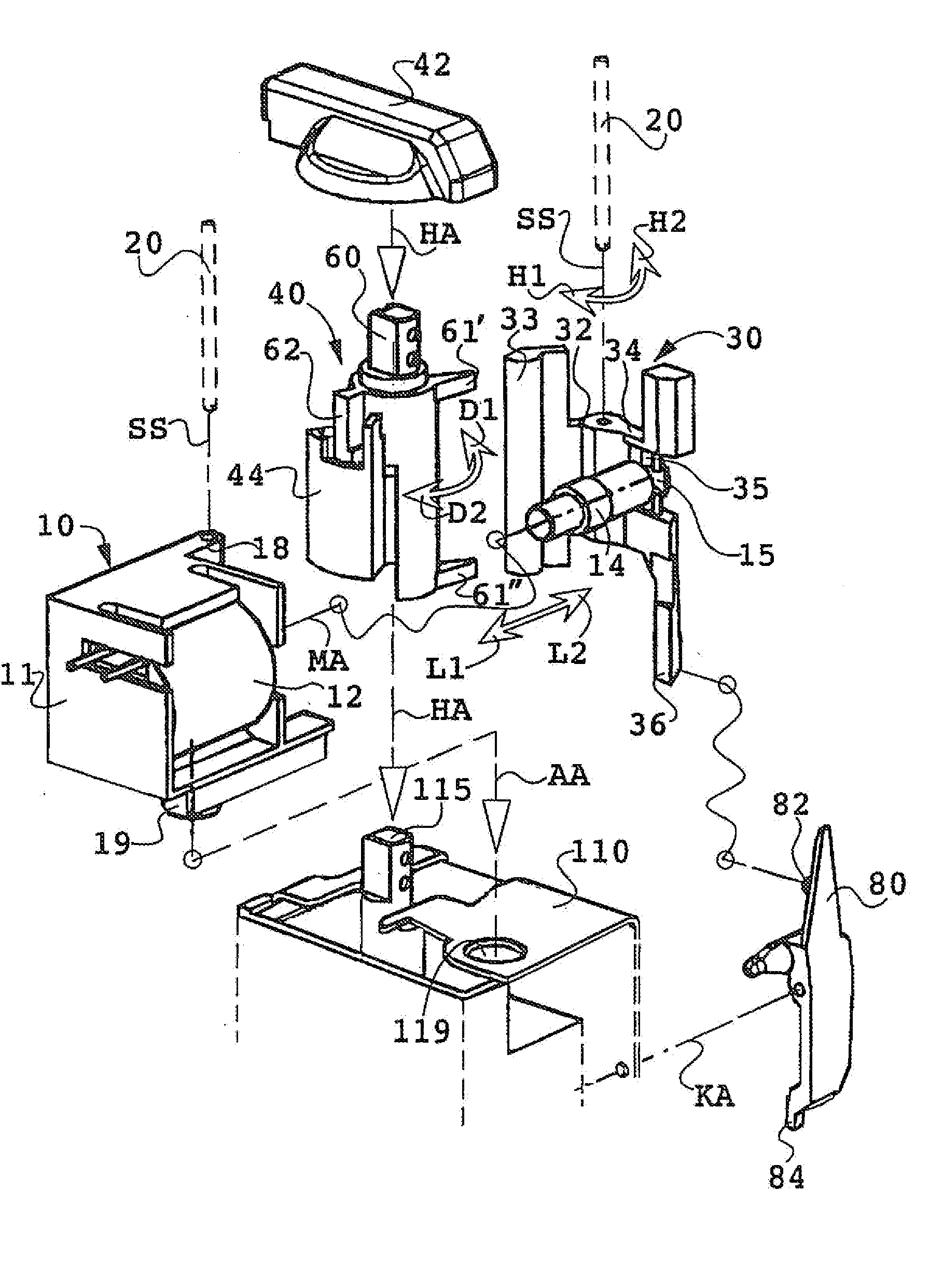
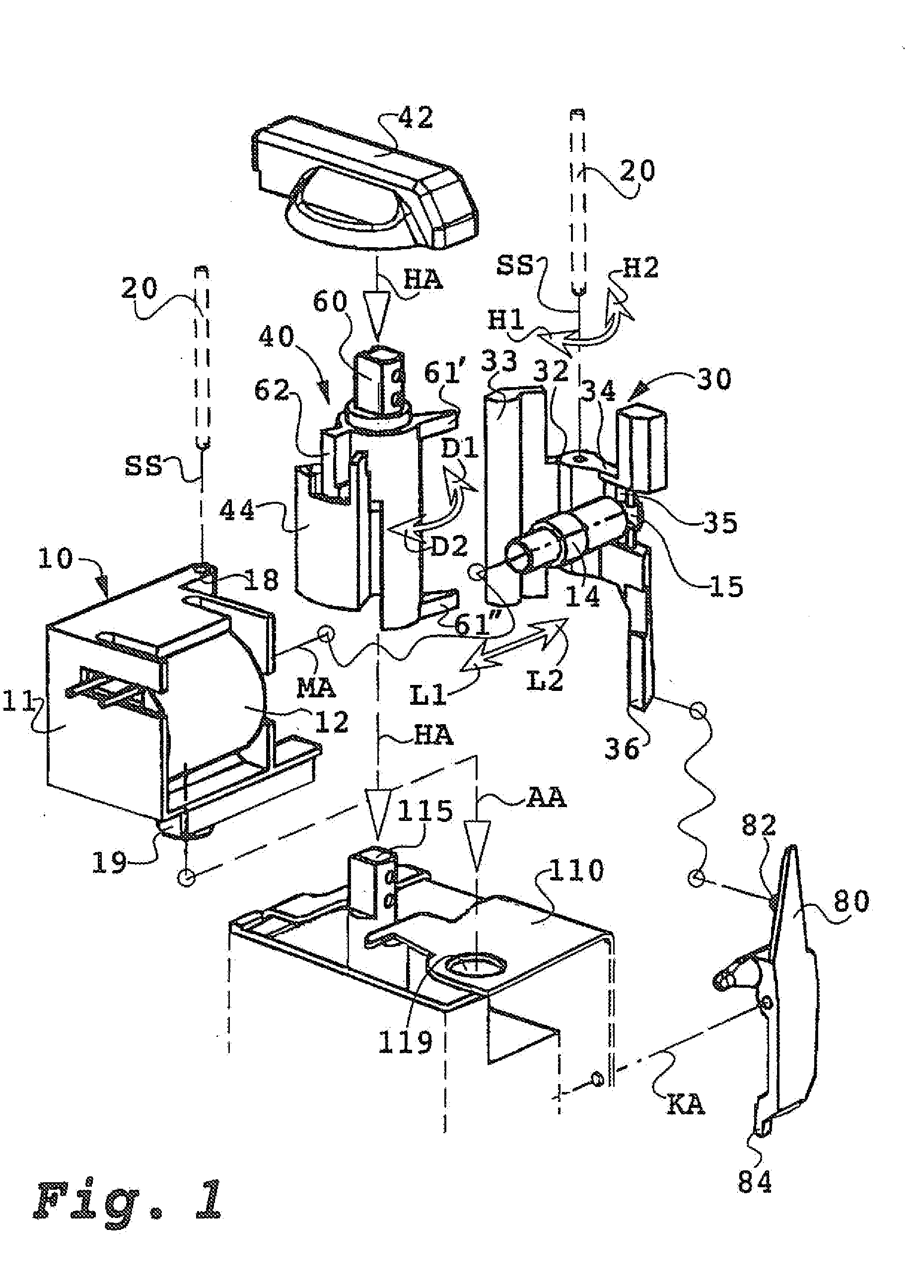
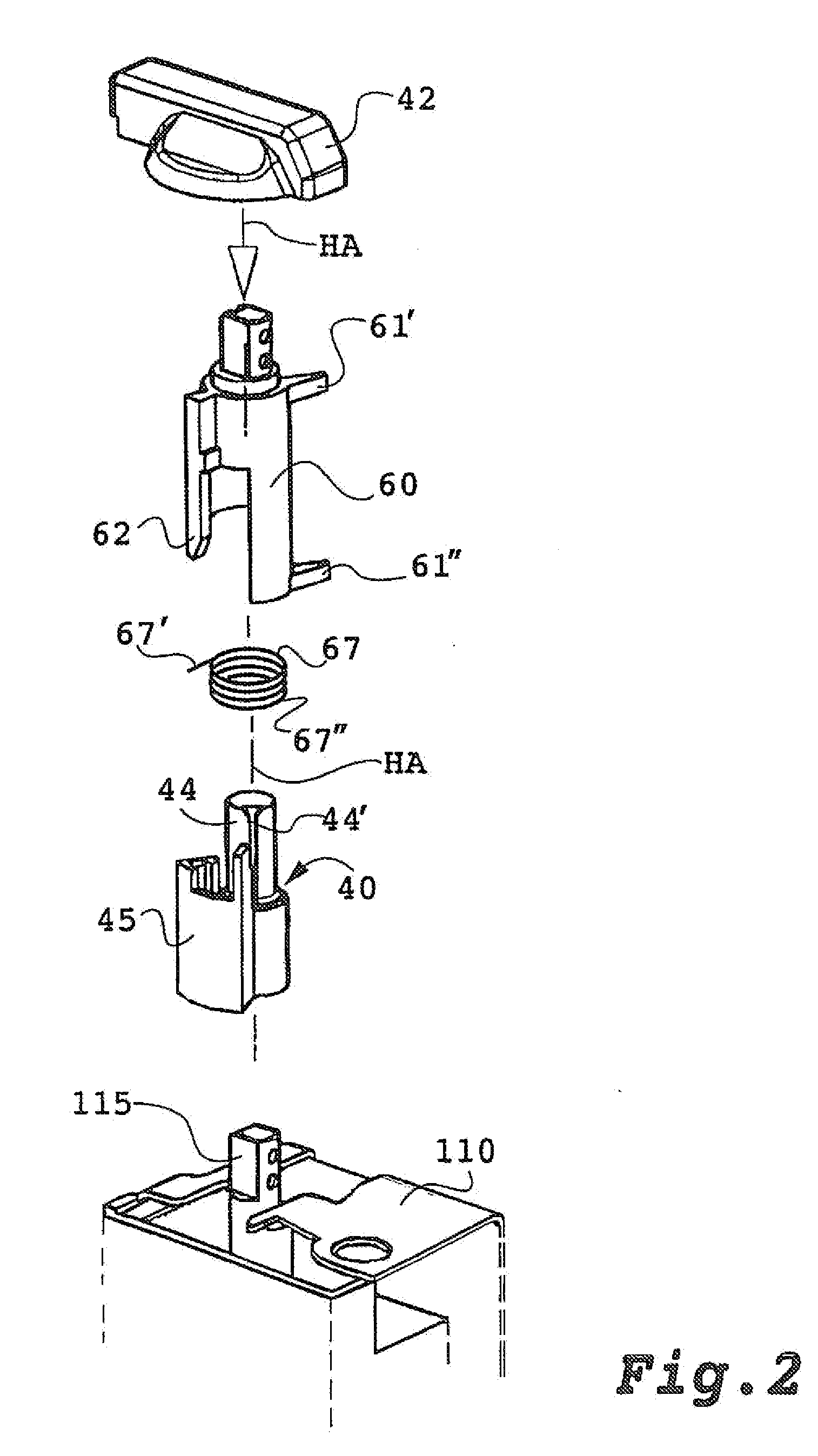
[0020]The actuating button 42 configured as a knob is affixed at the end of a drive shaft 40 and it extends beyond the housing (not shown here) of the circuit breaker. The drive shaft 40 is a multi-component assembly consisting of the actuating shaft 44 and the receiving shaft 60. This assembly is shown and described separately and comprehensively in FIG. 2.

[0021]From the outside, all that can be seen of the circuit breaker is the knob 42 that can be in an OFF position and in an ON position, which are offset from each other by 90°. In the ON position, the contacts are closed and the tripping unit can be activated. From this position, the contacts of the circuit breaker can be manually opened by turning the drive shaft 40 counterclockwise D1 by means of the knob 42. The drive shaft releases the latch in the switch mechanism and opens the contacts. For the manual switch-OFF, a brief rotation in the D1 direction is sufficient in order to actuate the latch. Rotation by a full 90° is not...


PUM


Abstract

An actuating unit or actuating mechanism and release for a circuit breaker. The magnetic mechanism of the release includes a magnet armature, which can move linearly in a magnet coil, is in the form of a tripping plunger and can be moved towards a permanent magnet counter to the force of a storage compression spring and is held fixedly by said permanent magnet in the case of a magnet coil through which no current is flowing. The tripping unit is in the form of a mechanical force store. After a tripping action, the mechanical force store needs to be reset manually again. For this purpose, a rotary movement of the drive shaft with an angular displacement of from 20 to 30 degrees takes place in the opposite direction to the ON switching rotary movement.

Description

[0001]The invention relates to an electrical circuit breaker with a protective function in case of a fault. Such circuit breakers comprise a switch mechanism, current paths with disconnectable contacts, an electromagnetic tripping unit, an electromagnetic control module that regulates in case of a fault, and a manual actuator unit for switching on and off as well as for resetting the tripping unit after it has been tripped. In response to a switch-OFF command, the tripping unit acts mechanically on the switch mechanism (for purposes of opening a biased latch or the contacts).BACKGROUND[0002]Circuit breakers of this type can be configured as motor circuit breakers or as automatic circuit breakers that are employed to switch a load on and off and that have a protective function by separating or interrupting the load in case of an electrical fault. Electrical faults can be short circuits, overcurrents or else undervoltages. Examples of typical circuit breakers are also residual current...

Claims


Application Information

Patent Timeline
Patent Type & Authority Applications(United States)
IPC IPC(8): H01H77/06
CPCH01H71/56H01H71/322
Inventor DAUER, KLAUSBAUJAN, GUENTERJUELICH, ANKE
Owner KLOCKNER-MOELLER GMBH
Why Eureka
Try Eureka