
Image sensor, focus detection device, focus adjustment device and image-capturing apparatus

a technology of image sensor and focus detection device, which is applied in the direction of instruments, television systems, and scanning details of television systems, can solve the problems of poor image quality and the extent of error of the pixel signal calculated for the position that would otherwise be occupied by the blue pixel to be bound to be significant, and achieve poor image quality

Active Publication Date: 2009-07-02
NIKON CORP
View PDF1 Cites 44 Cited by
  • Summary
  • Abstract
  • Description
  • Claims
  • Application Information

AI Technical Summary

Benefits of technology

[0006]There is an issue yet to be effectively addressed in the image-capturing apparatuses in the related art described above in that an image signal at a position occupied by a focus detection pixel may sometim...

Problems solved by technology

There is an issue yet to be effectively addressed in the image-capturing apparatuses in the related art described above in that an image signal at a position occupied by a focus detection pixel may sometimes have to be calculated through pixel interpolation executed based upon the pixel signals at imaging pixels present over significant distances from the focus detection pixel position to result in poorer image quality.
This means that if an image of a blue straight line or a blue edge is superimposed over the row of focus detection pixels, the extent of error of the pixel signal calculated for the position that would otherwise be occupied by the blue pixel is bound to be significant.

Method used


Image

  • Image sensor, focus detection device, focus adjustment device and image-capturing apparatus
  • Image sensor, focus detection device, focus adjustment device and image-capturing apparatus
  • Image sensor, focus detection device, focus adjustment device and image-capturing apparatus

Examples


Embodiment Construction

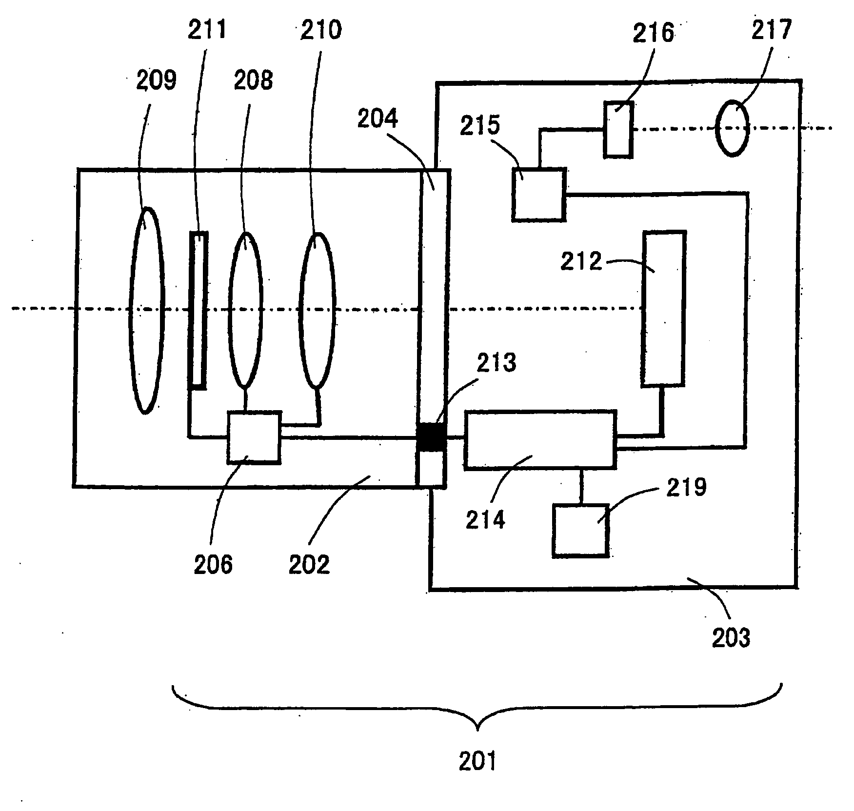
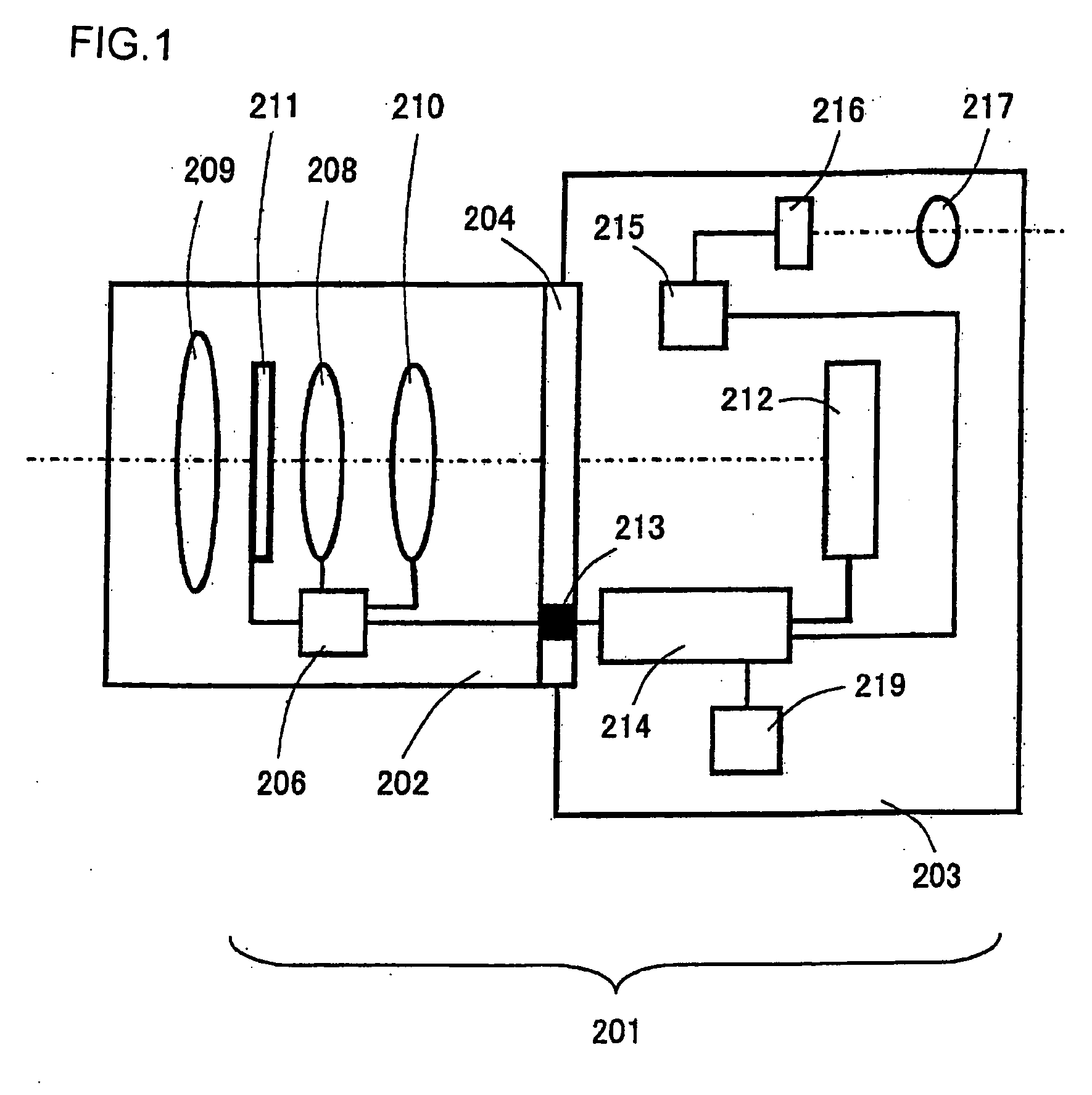
[0039]A digital still camera that allows the use of interchangeable lenses is now described as an embodiment of the image sensor and the image-capturing apparatus according to the present invention. FIG. 1 is a lateral sectional view showing the structure adopted in a digital still camera. (image-capturing apparatus) 201 achieved in the embodiment. The digital still camera 201 includes an interchangeable lens 202 and a camera body 203. The interchangeable lens 202 is mounted at the camera body 203 via a mount unit 204. Interchangeable lenses constituted with various photographic optical systems can be mounted at the camera body 203 via the mount unit 204.

[0040]The interchangeable lens 202 includes a lens 209, a zooming lens 208, a focusing lens 210, an aperture 211 and a lens drive control device 206. The lens drive control device 206 is constituted with a microcomputer, a memory, a drive control circuit and the like (none shown). It engages in communication with a body drive contro...


PUM


Abstract

An image sensor includes: a plurality of imaging pixel rows, which include a plurality of types of imaging pixels with varying spectral sensitivity characteristic that are arrayed two-dimensionally based upon a first spectral sensitivity characteristics array pattern; and at least one non-imaging pixel row, which includes a plurality of non-imaging pixels that are disposed in place of some of the plurality of types of imaging pixels in the plurality of imaging pixel rows. The plurality of imaging pixel rows include adjacent imaging pixel rows made up with the plurality of types of imaging pixels and set adjacent to the non-imaging pixel row; and the adjacent imaging pixel rows assume a second spectral sensitivity characteristics array pattern different from the first spectral sensitivity characteristics array pattern, so that spectral sensitivity characteristics different from spectral sensitivity characteristics achieved in conformance to the first spectral sensitivity characteristics array pattern are achieved via specific imaging pixels making up part of the adjacent imaging pixel rows.

Description

[0001]This non-provisional application claims the benefit of U.S. Provisional Application No. 61 / 009,146 filed Dec. 27, 2007. This application also claims priority from Japanese Application No. 2007-334124 filed Dec. 26, 2007. The disclosure of each of the earlier applications is incorporated herein by reference in its entirety.BACKGROUND OF THE INVENTION[0002]1. Field of the Invention[0003]The present invention relates to an image sensor, a focus detection device, a focus adjustment device and an image-capturing apparatus.[0004]2. Description of Related Art[0005]There are image-capturing apparatuses known in the related art such as that disclosed in Japanese Laid Open Patent Publication No. 2007-279597, equipped with an image sensor with focus detection pixels disposed in part of an imaging pixel array, in which image signals at positions occupied by the focus detection pixels are generated through pixel interpolation executed based upon pixel signals at imaging pixels present arou...

Claims


Application Information

Patent Timeline
IPC IPC(8): G03B13/00
CPCG06T3/00H04N9/045H04N5/23212H04N23/672H04N25/704H04N23/843H04N25/136H04N25/134H04N25/702
Inventor KUSAKA, YOSUKE
Owner NIKON CORP
Learn More