
Method and apparatus for conveying antenna configuration information

a technology of antenna configuration and information, applied in the field of communication, can solve the problems of user equipment, data loss and latency, inconvenient demodulation, etc., and achieve the effect of reliable demodulation and interpretation

Active Publication Date: 2009-07-09
NOKIA CORP
View PDF3 Cites 94 Cited by
  • Summary
  • Abstract
  • Description
  • Claims
  • Application Information

AI Technical Summary

Benefits of technology

[0012]A method and apparatus are therefore provided in accordance with embodiments of the present invention to provide additional information relating to an antenna configuration and / or a transmission diversity scheme. As such, embodiments of the method and apparatus permit a recipient to reliably distinguish between a plurality of antenna configurations and / or transmission diversity schemes, thereby permitting the transmitted data to be more reliably demodulated and interpreted. Moreover, embodiments of the method and apparatus are configured to provide this additional information without transmitting any additional bits or otherwise adding to the overhead associated with the transmission of the data.

Problems solved by technology

However, there is evidence that such a procedure is not reliable at the low signal-to-noise ratio conditions where the PBCH is designed to operate.
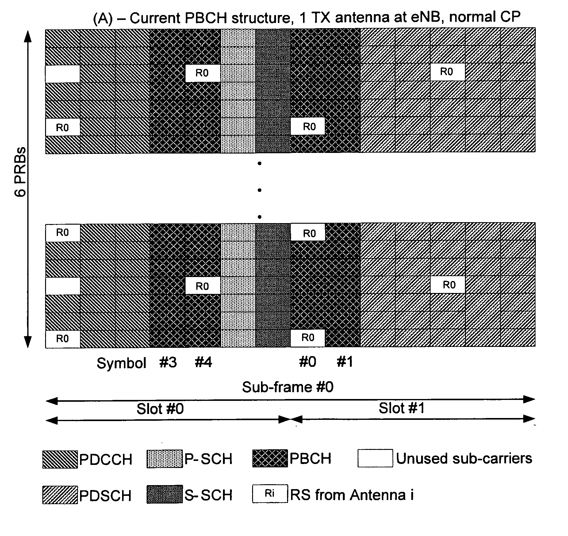
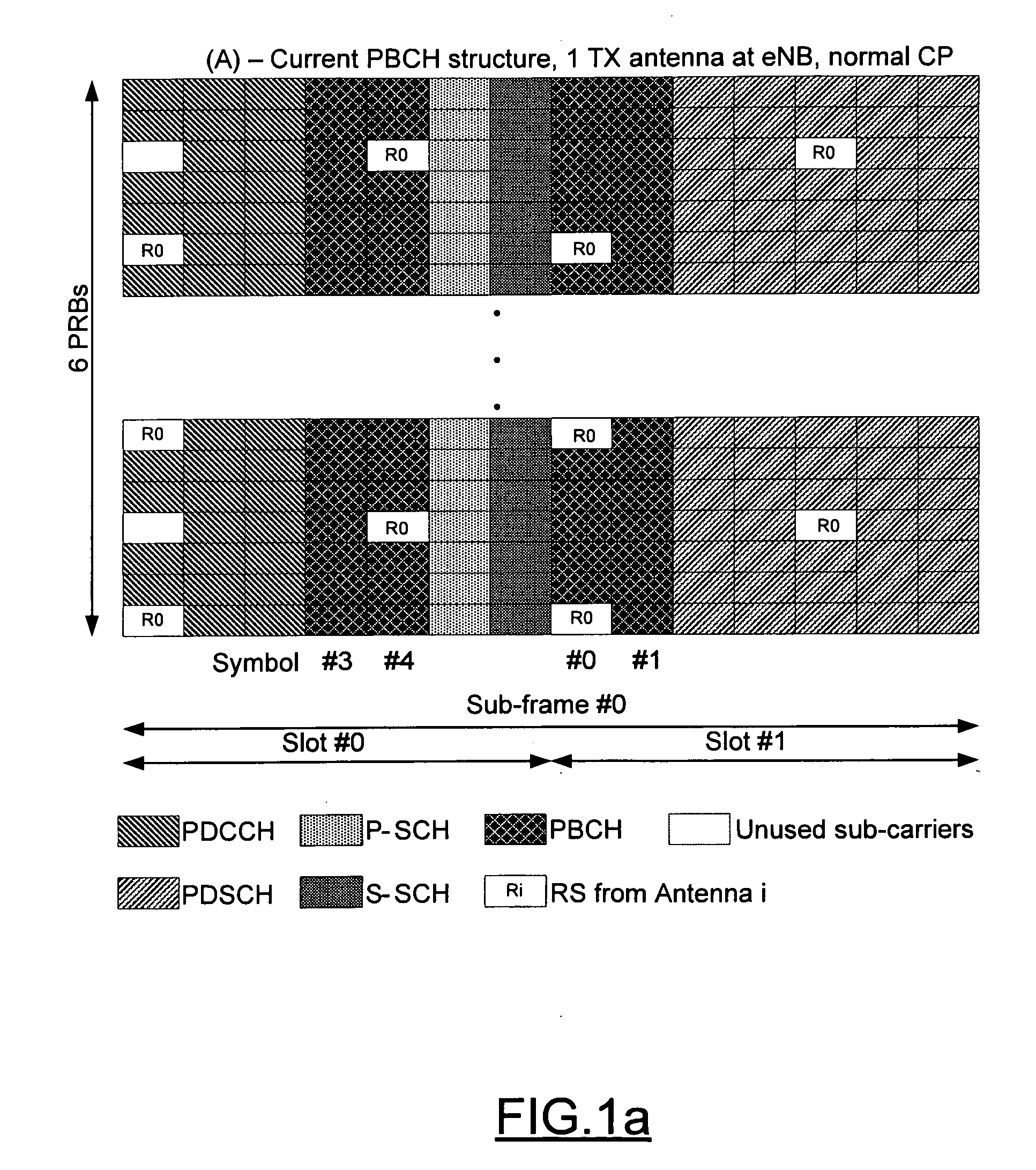
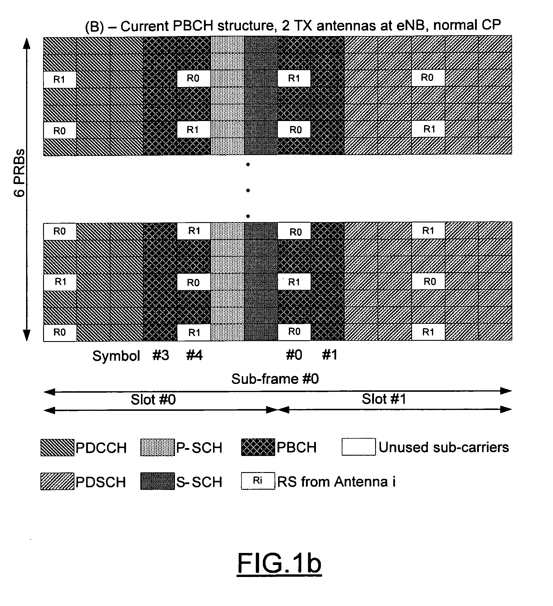
However, while antenna configuration information can be derived from the reference signals, the user equipment is, at least initially, not aware of the antenna configuration and / or the transmission diversity scheme prior to receiving and demodulating the PBCH.
Further, since the antenna configuration information is needed to properly demodulate data and control channels, data loss and latency can result if the user equipment incorrectly identifies the antenna configuration and / or the transmission diversity scheme or if the user equipment is slow in identifying the antenna configuration and / or the transmission diversity scheme.
These assumptions of antenna configuration and / or transmission diversity scheme may be made prior to, or during demodulation of the PBCH and may not always be correct.
Similarly, noise in the received signal may also affect the user equipment's assumption regarding an antenna configuration and / or transmission diversity scheme.
The error rate associated with the user equipment's assumption of the antenna configuration and / or the transmission diversity scheme or at least the adverse consequences which flow from an incorrect assumption can be exacerbated due to the conventional mapping of the PBCH within a sub-frame.
As such, the similarities of the PBCH for a two antenna configuration and a four antenna configuration can increase the error rate associated with the user equipment's assumption of the antenna configuration and / or the transmission diversity scheme or at least the adverse consequences which flow from an incorrect assumption.
As such, an incorrect selection of a diversity scheme implemented to decode the PBCH can result in a proper decoding of the PBCH.
The incorrect selection may then be used further which can result in substantial errors in communications.

Method used


Image

  • Method and apparatus for conveying antenna configuration information
  • Method and apparatus for conveying antenna configuration information
  • Method and apparatus for conveying antenna configuration information

Examples


Embodiment Construction

[0035]Embodiments of the present invention will now be described more fully hereinafter with reference to the accompanying drawings, in which some, but not all embodiments of the invention are shown. Indeed, the invention may be embodied in many different forms and should not be construed as limited to the embodiments set forth herein; rather, these embodiments are provided so that this disclosure will satisfy applicable legal requirements. Like reference numerals refer to like elements throughout.

[0036]FIG. 2 illustrates a block diagram of a mobile terminal 10 that would benefit from embodiments of the present invention. It should be understood, however, that a mobile telephone as illustrated and hereinafter described is merely illustrative of one type of mobile terminal (also known as user equipment) that would benefit from embodiments of the present invention and, therefore, should not be taken to limit the scope of embodiments of the present invention. While one embodiment of th...


PUM


Abstract

A method, apparatus and computer program product are provided for conveying information regarding the antenna configuration and / or the transmission diversity scheme to a recipient, such as a mobile device. In particular, information regarding the antenna configuration and / or the transmission diversity scheme can be conveyed by appropriately mapping a physical broadcast channel within a sub-frame so as to include reference signals indicative of different antenna configurations or transmission diversity schemes. Alternatively, masking, such as cyclic redundancy check masking, can be used to provide information regarding the antenna configuration and / or the transmission diversity scheme.

Description

TECHNOLOGICAL FIELD[0001]Embodiments of the present invention relate generally to communications between a network entity, such as a base station, and a recipient, such as a mobile terminal, and, more particularly, relate to a method and apparatus for conveying antenna configuration information.BACKGROUND[0002]In conventional wireless communications systems, mobile devices or other user equipment transmit information to a network, and receive information from a network, such as via a base station. In some networks, the base stations or other network entities which transmit information to the user equipment may include different antenna configurations, such as different numbers of antennas, e.g., one antenna, two antennas or four antennas, and / or may transmit the information in accordance with different transmission diversity schemes. In this regard, a base station with a single antenna may transmit information without any transmission diversity scheme, while base stations with two o...

Claims


Application Information

Patent Timeline
Patent Type & Authority Applications(United States)
IPC IPC(8): H04B1/02
CPCH04B7/0689H04B7/0619
Inventor RAAF, BERNHARDROMAN, TIMO ERICCHMIEL, MIESZKO
Owner NOKIA CORP
Learn More