Bending apparatus and method of bending a metal object

a metal object and bending apparatus technology, applied in metal working apparatus, manufacturing tools, shape safety devices, etc., can solve problems such as excessive scrap rates

Active Publication Date: 2009-07-16
GM GLOBAL TECH OPERATIONS LLC
View PDF14 Cites 29 Cited by
  • Summary
  • Abstract
  • Description
  • Claims
  • Application Information

AI Technical Summary

Benefits of technology

[0003]A method of bending a metal object, such as a tube, is provided that uses real time, closed-loop feedback of the actual springback of the object in order to modify the applied bending force or preprogrammed bending coordinates so that the final desired bend geometry is achieved. The variability of springback from object to object is thus accounted for and the number of objects that must be scrapped due to incorrect bends (over bend or under bend) is reduced. The method is carried out using an apparatus that includes a stationary base and a measuring device that is secured to the base. A rotatable bend die, a clamp die secured to the bend die and a pressure die movable with respect to the rotatable base, such as may be present on a rotary draw bender, are configured to bend metal objects and are also included in the apparatus. The pressure die acts on a wiper die. Additionally, a particular bend may require a mandrel to be placed between the wiper die and the metal object. The measuring device is operable to measure actual bend coordinates of metal objects bent by the dies. A controller is operatively connected to the dies, the base, and the measuring device and is configured to control the dies to bend the metal objects at least partly based on measured bend coordinates (i.e., feedback of actual springback) provided by the measuring device.

Problems solved by technology

Springback that is not properly predicted or corrected can lead to excessive scrap rates.

Method used


Image

  • Bending apparatus and method of bending a metal object
  • Bending apparatus and method of bending a metal object
  • Bending apparatus and method of bending a metal object

Examples


Embodiment Construction

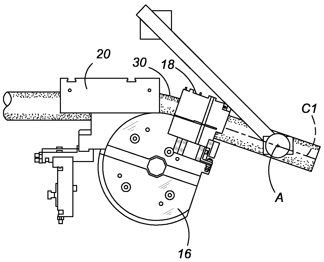
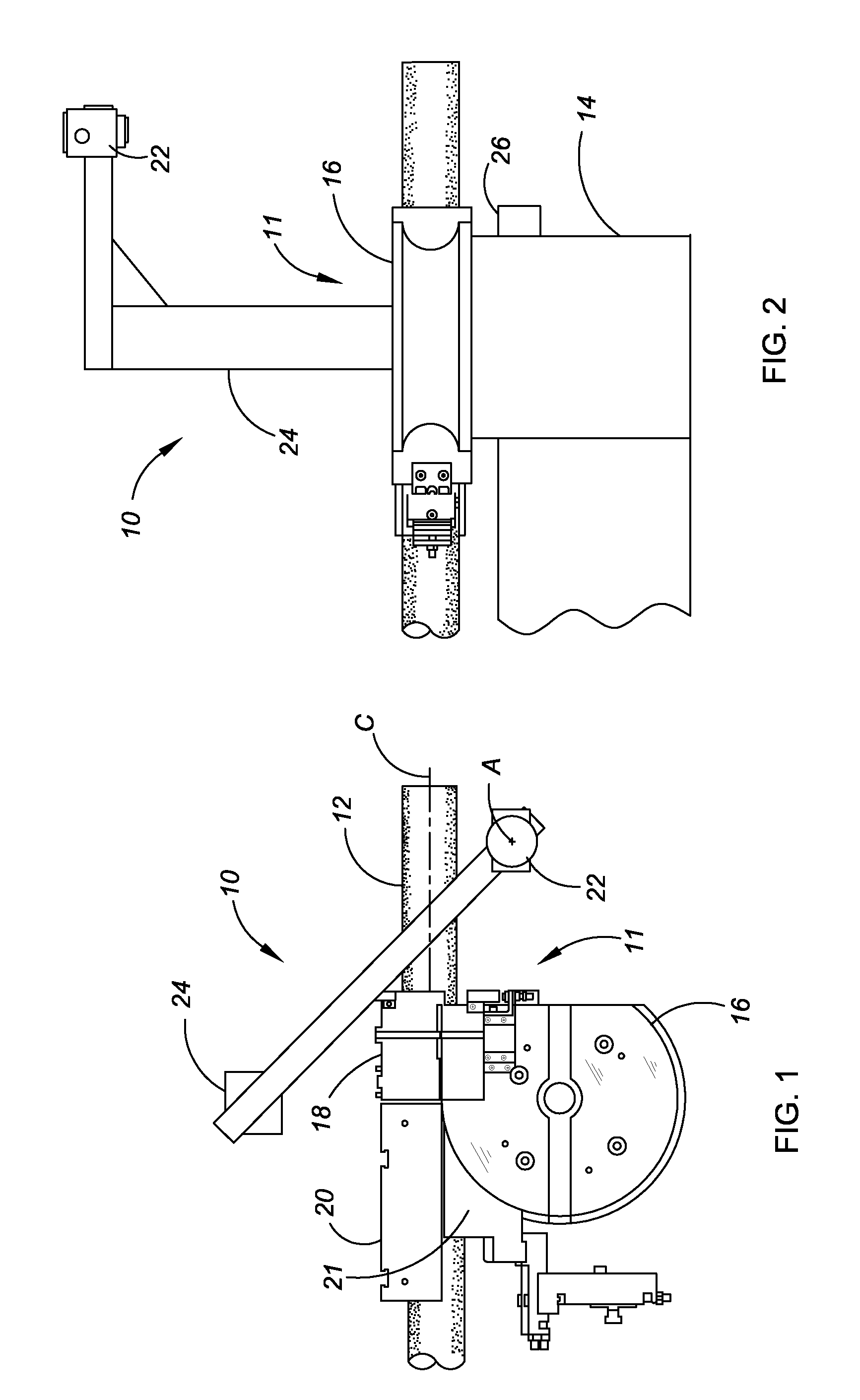
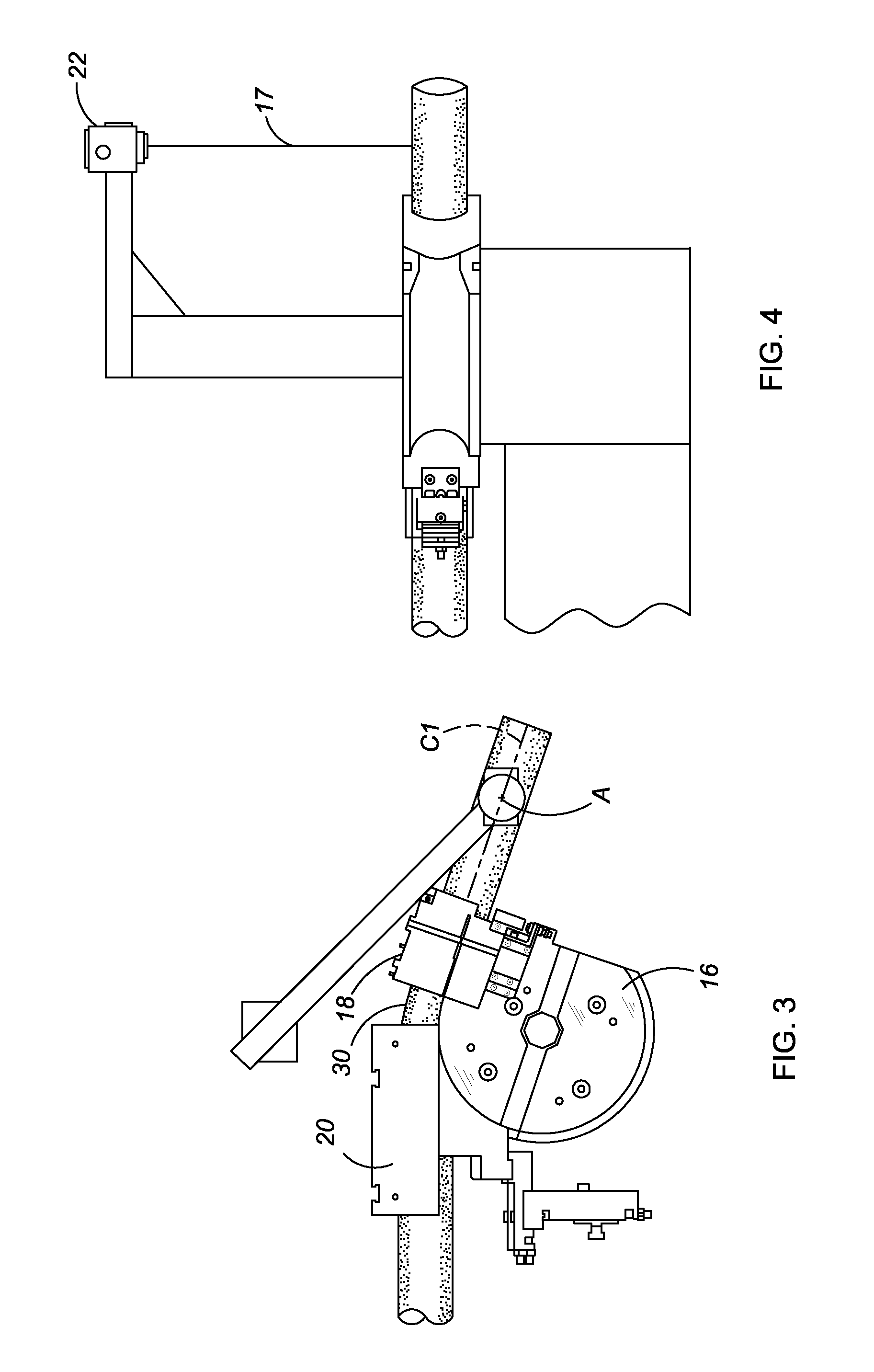
[0019]Referring to the drawings, wherein like reference numbers refer to like components, FIG. 1 shows an apparatus 10 for bending objects that includes a rotary draw bender 11 shown with a bendable object in the form of a metal tube 12. As can be seen in FIG. 2, the rotary draw bender 11 includes a stationary base 14 that supports a rotatable bend die 16. Bending is accomplished by clamping the tube 12 with a clamp die 18 against the bend die 16 and the pressure die 20 against a wiper die 21. The bend die 16 and the clamp die 18 are rotated as a unit starting plastic deformation of a first bend 30 in tube 12 (see FIG. 3). The pressure die 20 is delayed to prevent it from colliding with the clamp die 18 and to allow for material elongation on the inner side (compression side) of the bend as it flows against the wiper die 21 to prevent wrinkling. The apparatus 10 also includes a measuring device, optionally in the form of a video camera 22, positioned on a stationary support post 24 ...


PUM

PropertyMeasurementUnit
forceaaaaaaaaaa
releasing forceaaaaaaaaaa
applied forceaaaaaaaaaa

Abstract

A method of bending a metal object, such as a tube, is provided that uses real time, closed-loop feedback of the actual springback of the object in order to modify the applied bending force or preprogrammed bending coordinates so that the final desired bend geometry is achieved. The variability of springback from object to object is thus accounted for and the number of objects that must be scrapped due to incorrect bends (over bend or under bend) is reduced. The method is carried out using an apparatus such as a rotary draw bender with a measuring device operable to measure actual bend coordinates of metal objects bent by the bender. A controller is operatively connected to the bender and the measuring device and is configured to control the bender to bend the metal objects at least partly based on measured bend coordinates provided by the measuring device.

Description

TECHNICAL FIELD[0001]The invention relates to a method of bending a metal object that provides real time bend verification and correction, and a bending apparatus for same.BACKGROUND OF THE INVENTION[0002]While bending metal objects, such as metal tubes, many variables are encountered that must be accounted for to ensure that the desired final geometry is achieved. One such variable is the natural variation of sheet metal from coil to coil and its associated springback changes. Other contributors to processing variations include ambient temperature, machine temperature, lubrication, wear and tear of the bend tooling, and tooling setup. Metal tubes are formed from sheet metal rolled into a tubular shape and welded along an axial seam. “Springback” is the tendency of sheet metal (or a metal tube formed from a sheet) to lose some of its shape when it is removed from a die. As the die is released, the work piece ends up with less bend than that on the die (i.e., an “under bend”). The am...

Claims


Application Information

Patent Timeline
Patent Type & Authority Applications(United States)
IPC IPC(8): B21C51/00B21D7/14
CPCB21D7/024B21D7/14B21D7/12Y10S72/702
Inventor GHIRAN, MIKE M.MELLAS, SPYROS P.CRANTAS, WILLIAM M.MARKS, KEVIN R.FRIDDELL, DAVID R.LARSEN, PAUL D.
Owner GM GLOBAL TECH OPERATIONS LLC
Why Eureka
Try Eureka