
Container assembly

Active Publication Date: 2009-07-16
CASE-MATE +1
View PDF10 Cites 56 Cited by
  • Summary
  • Abstract
  • Description
  • Claims
  • Application Information

AI Technical Summary

Benefits of technology

[0011]It is yet another object of the present invention to provide a container assembly having stacking patterns that are more resistant to wear and damage.
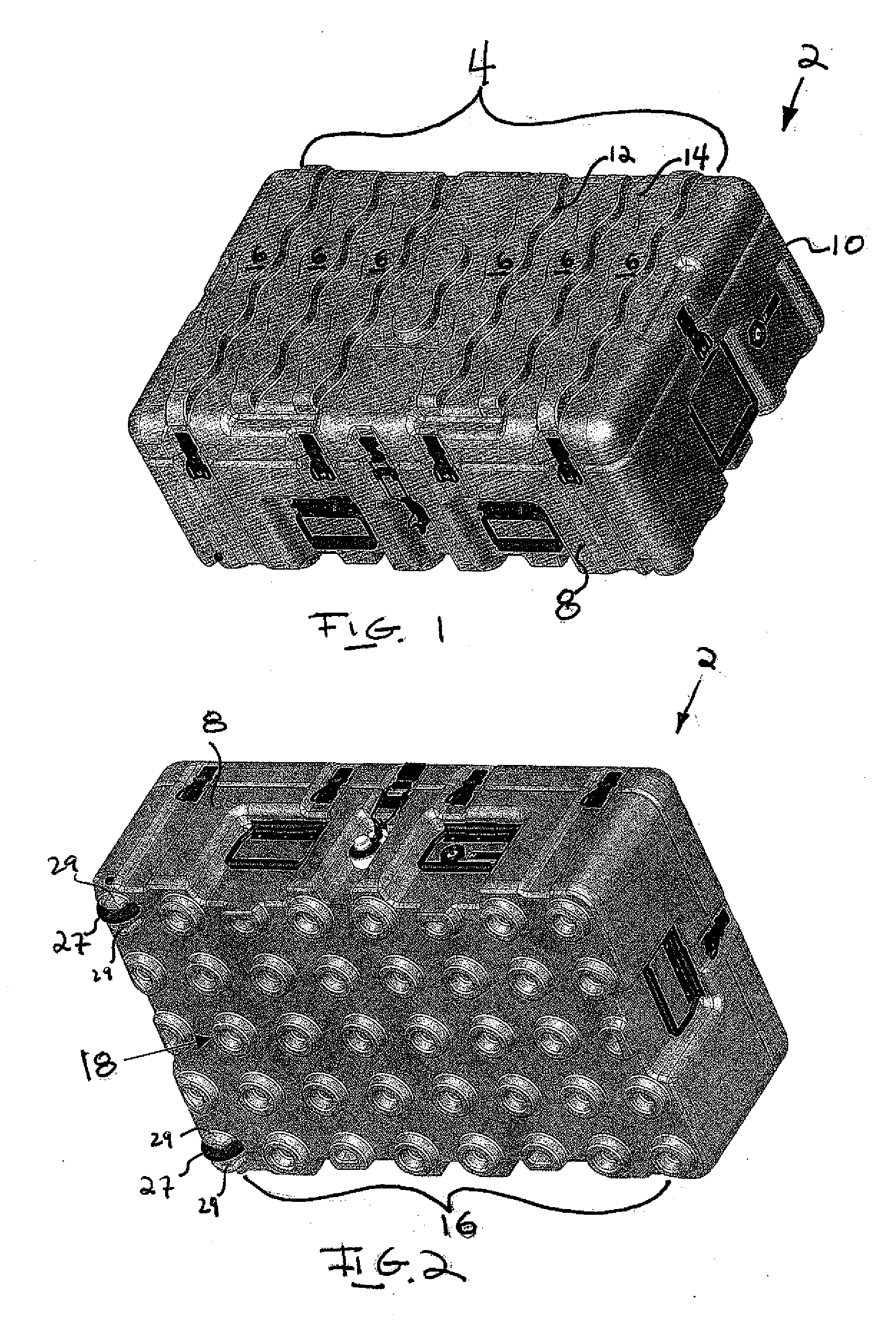
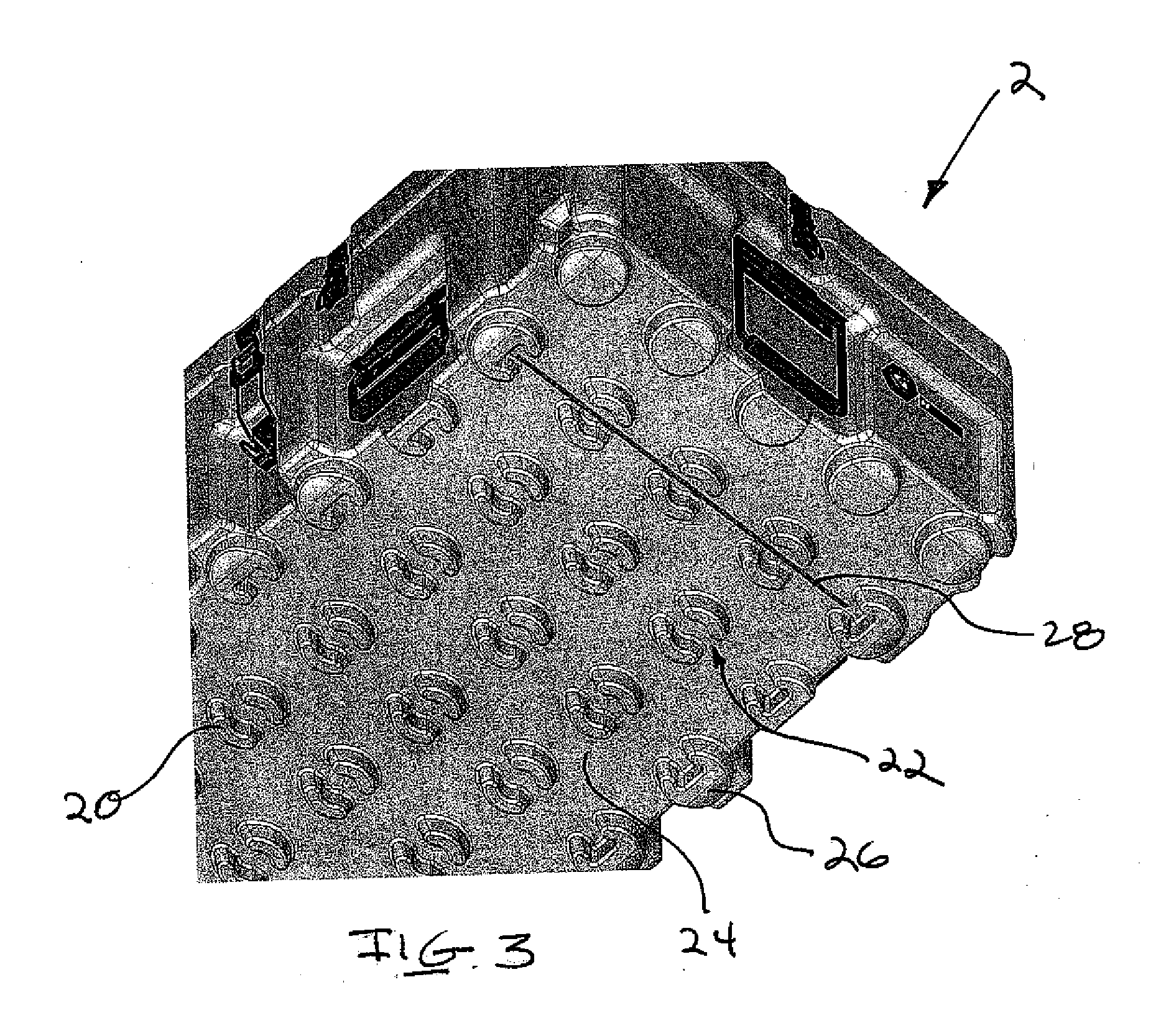
[0015]An embodiment of the inventive container assembly for the storage and transport of goods includes a first portion having an interior with a substantially flat interior bottom surface. The assembly further includes a second portion pivotally connected to the first portion. The first portion has an outer surface that includes a first stacking pattern and the second portion has an outer surface that includes a second stacking pattern different from the first stacking portion and configured to engage the first stacking pattern enabling the container assembly to be bi-directionally stacked on another of the container assemblies.
[0016]An embodiment of the inventive locking mechanism for a container assembly includes a hinged leaf portion having a hooked end. The leaf portion is pivotally attached to a leaf bracket which is, in turn, secured to the container assembly. The locking mechanism further includes a base portion also secured to the container assembly. The base portion has a lever with an engagement end for engagement with the hooked end. The lever is pivotally secured to the base portion. The lever may be moved to bring the engagement end into engagement with the hooked end to secure the locking mechanism and, when the locking mechanism is secured, the lever and the leaf portion cover and protect the fasteners that secure the leaf portion and the base portion to the container to prevent unauthorized access to an interior of said container assembly.

Problems solved by technology

In addition, known containers also typically employ patterns which are limited to being uni-directional in their stacking ability and frequently employ patterns that contain ‘hard’, or sharp edges.

Method used


Image

  • Container assembly
  • Container assembly
  • Container assembly

Examples


Embodiment Construction

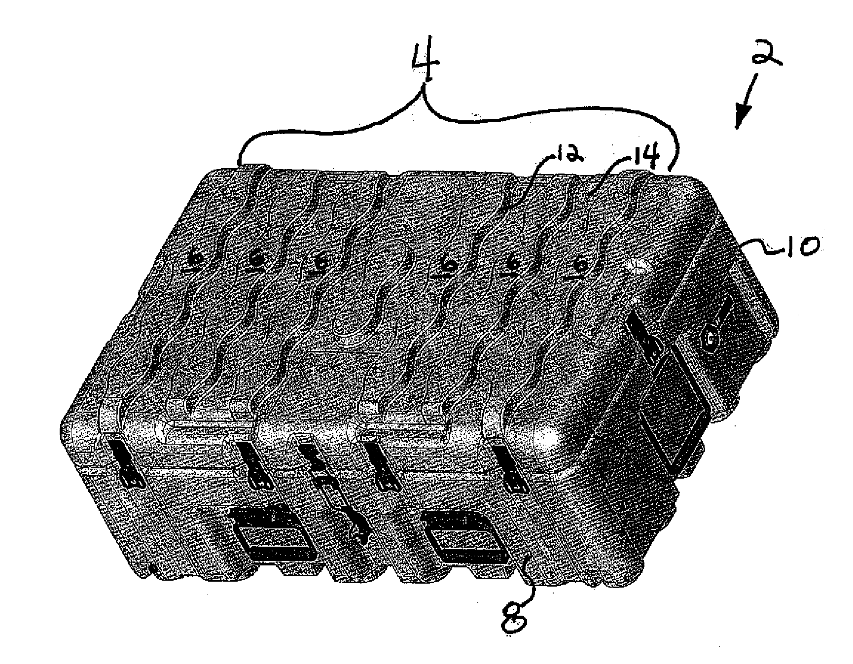
[0027]FIGS. 1-9E illustrate a container assembly according an embodiment of the present invention. As shown in FIGS. 1 and 2, the inventive container assembly 2 includes structural profiles formed on opposing sides of the container. In particular, one side of the container 2 defines a first stacking profile 4 that includes a series of wavy ribs or ridges 6, extending from one lateral side of the container 8, to the other 10. When located side-by-side with one another, the wavy ridges 6 define a series of wave-like profiles 12 that create laterally extending channels or valleys 14 therebetween.

[0028]As shown, the raised wavy ridges 6 undulate in a sinusoidal fashion along their lateral axis, thereby forming a series of apexes and depressions along the length of the ridges 6. The wavy ridges 6 are oriented on the container 2 such that the apexes of adjacent wavy ridges 6 are opposed to one another, thus creating a repeating series of wide and narrow, i.e., convex and concave, sections...


PUM


Abstract

A container assembly for the storage and transport of goods, the assembly including a first portion having an interior with a substantially flat interior bottom surface. The assembly further includes a second portion pivotally connected to the first portion. The first portion has an outer surface that includes a first stacking pattern and the second portion has an outer surface that includes a second stacking pattern which is different from the first stacking pattern and configured to engage the first stacking pattern enabling the container assembly to be bi-directionally stacked on another of the container assemblies.

Description

CROSS-REFERENCE TO RELATED APPLICATION[0001]This application claims priority to U.S. Provisional Application No. 61 / 021,195, filed on Jan. 15, 2008, titled “CONTAINER ASSEMBLY,” which is hereby incorporated by reference in its entirety.FIELD OF THE INVENTION[0002]This invention relates, in general, to a container assembly, and deals more particularly with a container assembly having a unique, utilitarian pattern formed on opposing sides of the container assembly, whereby the pattern provides increased stacking and attachment-point advantages.BACKGROUND OF THE INVENTION[0003]Containers of various shapes, sizes and configurations have been employed to accommodate all manner of storage and transportation needs. Typically, in the case of containers primarily utilized to transport items, it is often necessary to protect these items from impact and / or environmental damage, as well as to make the container suitable for stacking and storage during transportation.[0004]Towards this end, it h...

Claims


Application Information

Patent Timeline
IPC IPC(8): B65D21/02B65D55/14
CPCA45C13/18E05C19/14B65D21/0223
Inventor PATSTONE, CHRISTOPHER H.STRZEGOWSKI, JR., JOSEPH C.SMIAROSKI, STEPHEN R.JENNY, DAVID
Owner CASE-MATE
Learn More