
Method and apparatus for selecting an encryption integrated circuit operating mode

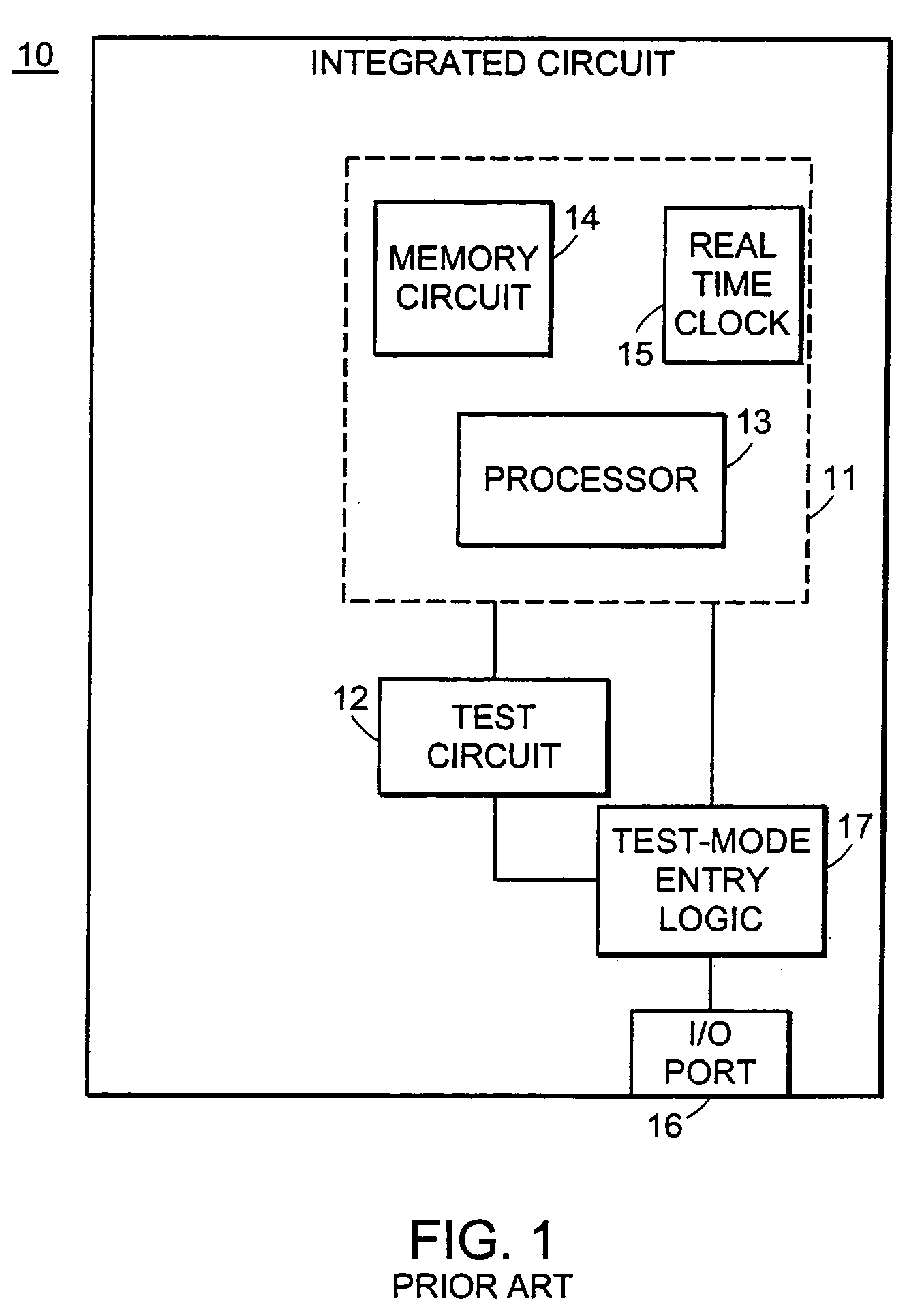
Inactive Publication Date: 2006-03-07
TAIWAN SEMICON MFG CO LTD
View PDF15 Cites 11 Cited by
  • Summary
  • Abstract
  • Description
  • Claims
  • Application Information

AI Technical Summary

Benefits of technology

[0009]In an attempt to overcome these and other limitations of the prior art, it is an object of the present invention to provide a system and a method for the secure switching of an encryption processor of a cryptographic system between a first and a second mode of operation, wherein access to secure electronic keys stored within the cryptographic system is prevented.

Problems solved by technology

However, a disadvantage of dynamic entry is that the test mode may be accidentally entered if the test mode condition is latched into the device when the test mode is not desired.
Of course, a drawback of static test mode entry is that unintentional entry into a test mode can result from overshoots or undershoots on pins during normal operation in noisy systems.
Further, in addition to denying unauthorized access to secure data by an unintended third party, the authorized and intended user of the integrated circuit must also be other than able to probe the contents of the integrated circuit when the integrated circuit is operating in test mode.
In fact, a known method to secure data occurs upon detecting an attempt to probe the contents of the integrated circuit, using either electronic or mechanical means, results in clearing, deactivation and / or self-destruction of the encryption unit.
When such data includes financial information or information of a personal and confidential nature, then the potential also exists for the unauthorized third party to cause serious inconvenience and / or financial loss to a legitimate user of the encryption unit.
Even the compromise of a single bit of a secure key, for instance a 128-bit secure encryption key, reduces the effectiveness of the secure key by a significant factor.
Further, it will be obvious to one of skill in the art that since computer processing power continues to double approximately every two years, the secure keys that are in use today are susceptible to key compromise in the future.
Of course, the inability to probe the electronic data contents of a prior art encryption unit precludes the possibility of performing legitimate and often necessary trouble-shooting procedures.
In the case of an integrated circuit that is used in an encryption unit, such trouble-shooting is of particular importance since any data that is provided to the unit for encryption is permanently unrecoverable if the encryption unit performs within other than as expected.
In particular, trouble-shooting functions are often necessary when data that was previously provided to an encryption unit for encryption is other than recoverable by an intended recipient, and when a new encryption unit is added to a computer system.

Method used


Image

  • Method and apparatus for selecting an encryption integrated circuit operating mode
  • Method and apparatus for selecting an encryption integrated circuit operating mode
  • Method and apparatus for selecting an encryption integrated circuit operating mode

Examples


third embodiment

[0045]Of course, the present invention provides other than a true test mode, for instance it is other than possible to probe the contents of the first data bank 44a that stores secure data. The user performing the test operation must assume that the first data bank 44a works correctly, and that a particular problem is in the actual data processing performed by the processor 43. Conveniently, the user is able to complete the test functions within the pseudo-test mode and avoid permanent erasure of the secure electronic keys that are required when the circuit 40 is switched back to work mode. Optionally, a true test mode is provided for certain pathways of the circuit 40 in addition to the pseudo-test mode. Of course, in such case, the pathways are necessarily clear when the integrated circuit initiates test mode thereof.

fourth embodiment

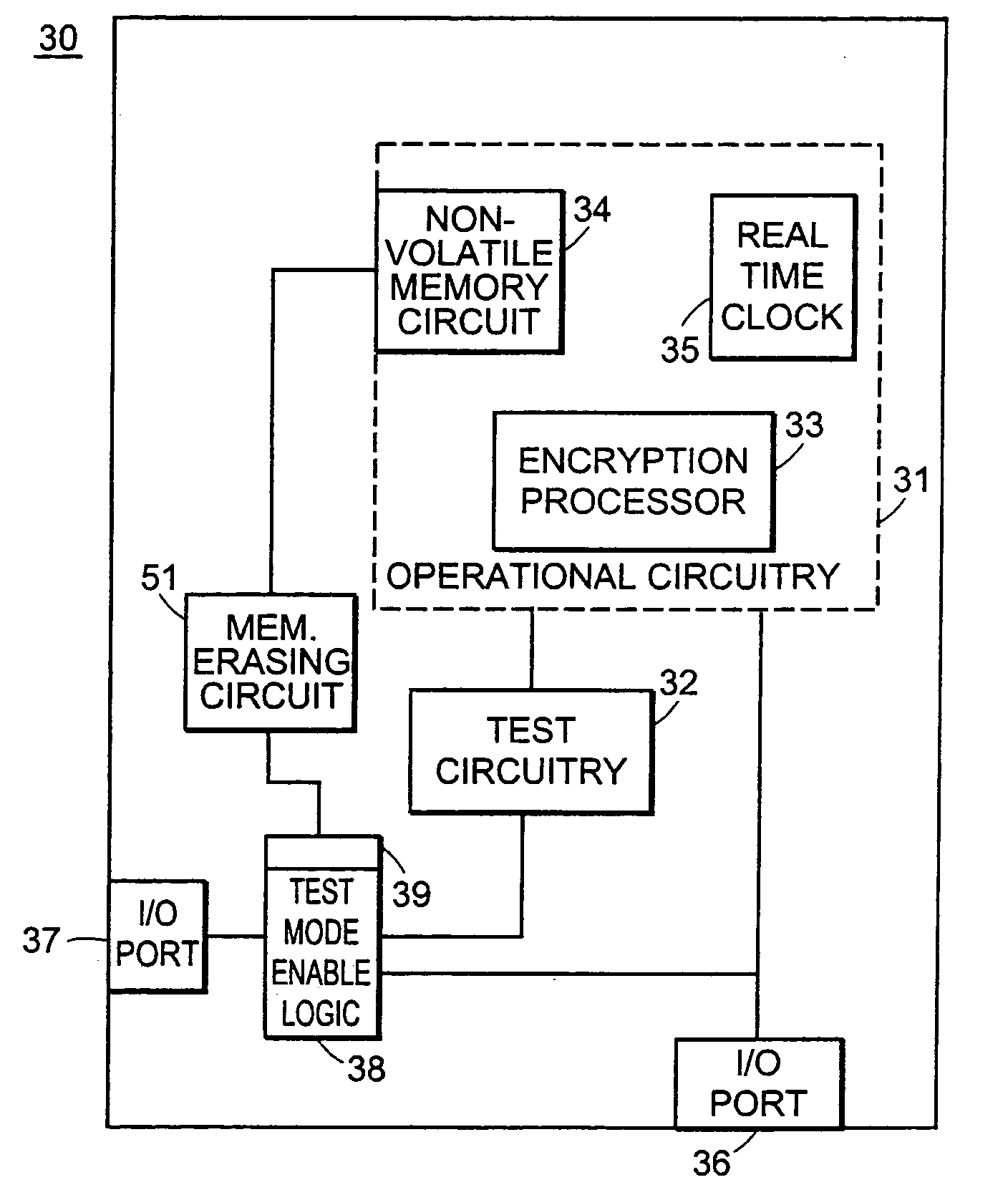
[0046]Referring to FIG. 5, a system for test mode entry of an integrated circuit according to the present invention is shown generally at 60. A first integrated circuit 61 is in communication with a second other integrated circuit 62 via a secure communication channel 63. The integrated circuit 61 comprises operational circuitry 64 in electrical communication with test circuitry 65. The operational circuitry 64 includes an encryption processor 66 that is in operative communication with a memory circuit 67, for instance a non-volatile memory circuit. Optionally, the encryption processor 61 is in electrical communication with a real time clock 68, the real time clock 68 for providing a time value that is useable by the encryption processor 61 for performing time-stamping functions. Integrated circuit 61 further comprises a secure input / output port 69 for receiving secure data for processing by the encryption processor 66 and a test-mode input / output port 71 for receiving test data, fo...


PUM


Abstract

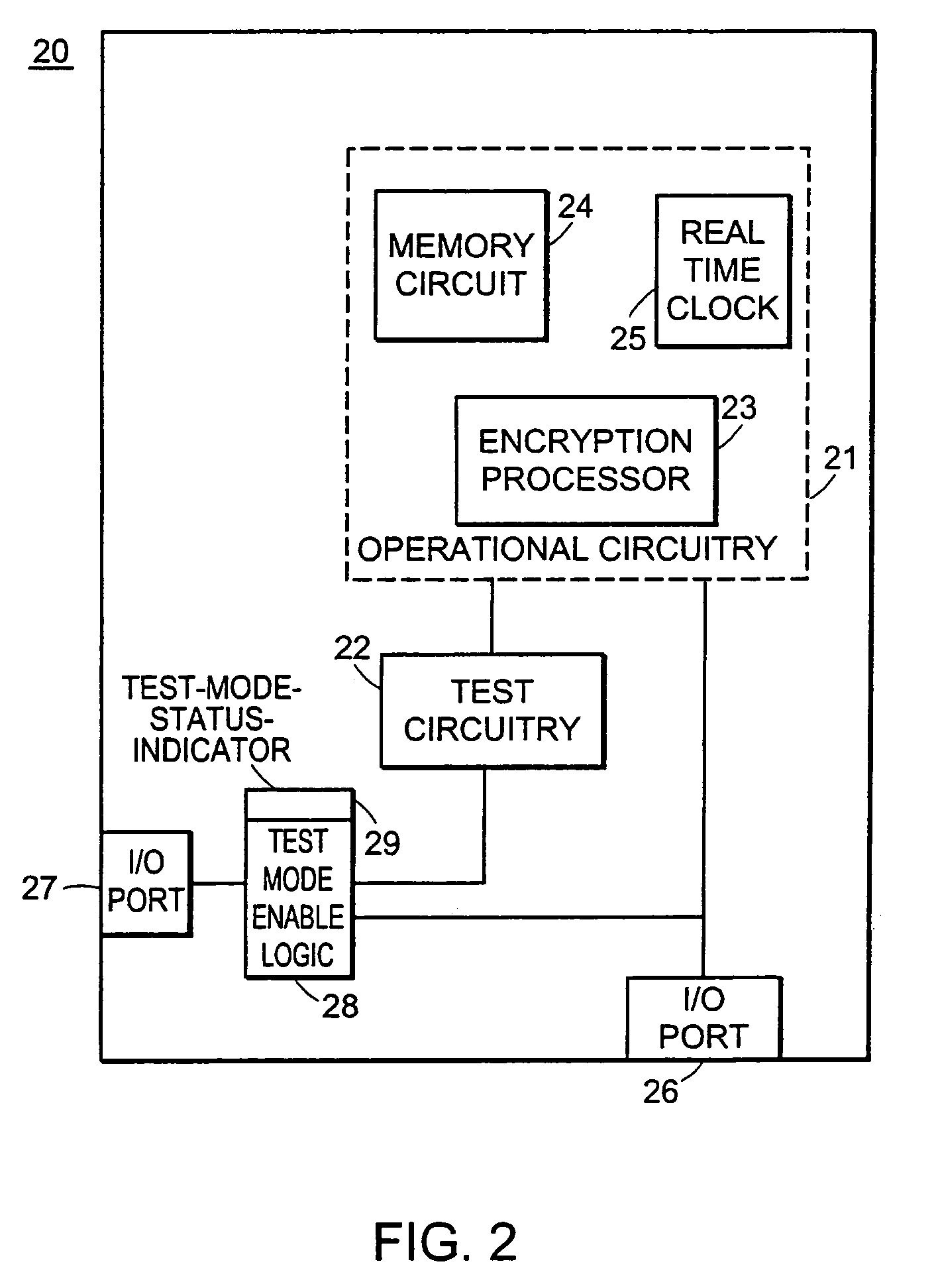
A method and circuit for preventing external access to secure data of an integrated circuit while supporting DFT is disclosed. In accordance with the method the integrated circuit is automatically placed into the test mode at integrated circuit power-up from a power-down state. At power up, secure data is other than present within a secure data-path of the integrated circuit. Access is provided to the secure data path via a second data path coupled with the first secure data-path. Via the access path, data other than secure data is provided to the integrated circuit, the data for performing test functions of the integrated circuit operating in the test mode. Once data other than secure data is provided to first secure data path, the test mode is terminated and access via other than the secure ports is disabled. The test mode is only re-entered by powering down the integrated circuit and re-initialising it.

Description

RELATED APPLICATIONS[0001]This application is a continuation of U.S. application Ser. No. 10 / 176,704, filed Jun. 20, 2002 is now a U.S. Pat. No. 6,664,803, which is a continuation of U.S. application Ser. No. 09 / 862,339 filed May 23, 2001 is now a U.S. Pat. No. 6,466,048. The entire teachings of the above applications are incorporated herein by reference.BACKGROUND OF THE INVENTION[0002]Integrated circuits are designed typically to operate in two distinct modes, but not at a same time, including a test mode, and a work mode for performing normal processing functions. Integrated circuits of this type are generally referred to as designed for test (DFT). When operating in the test mode, a designer has access to electronic information internal to the integrated circuit, including the contents of memory registers and the step-by-step microcode that is executed within the microprocessor. After a testing operation is completed, the designer switches the integrated circuit to the work mode...

Claims


Application Information

Patent Timeline
IPC IPC(8): H03K19/00H04L9/00G01R31/317G01R31/3185G06F21/00H04L9/10
CPCG01R31/31704G01R31/318588G06F21/74G01R31/318558G01R31/31719
Inventor GOODMAN, JAMES
Owner TAIWAN SEMICON MFG CO LTD
Learn More