
Computer start-up timing control device and method thereof

Inactive Publication Date: 2010-04-15
INVENTEC CORP
View PDF3 Cites 17 Cited by
  • Summary
  • Abstract
  • Description
  • Claims
  • Application Information

AI Technical Summary

Benefits of technology

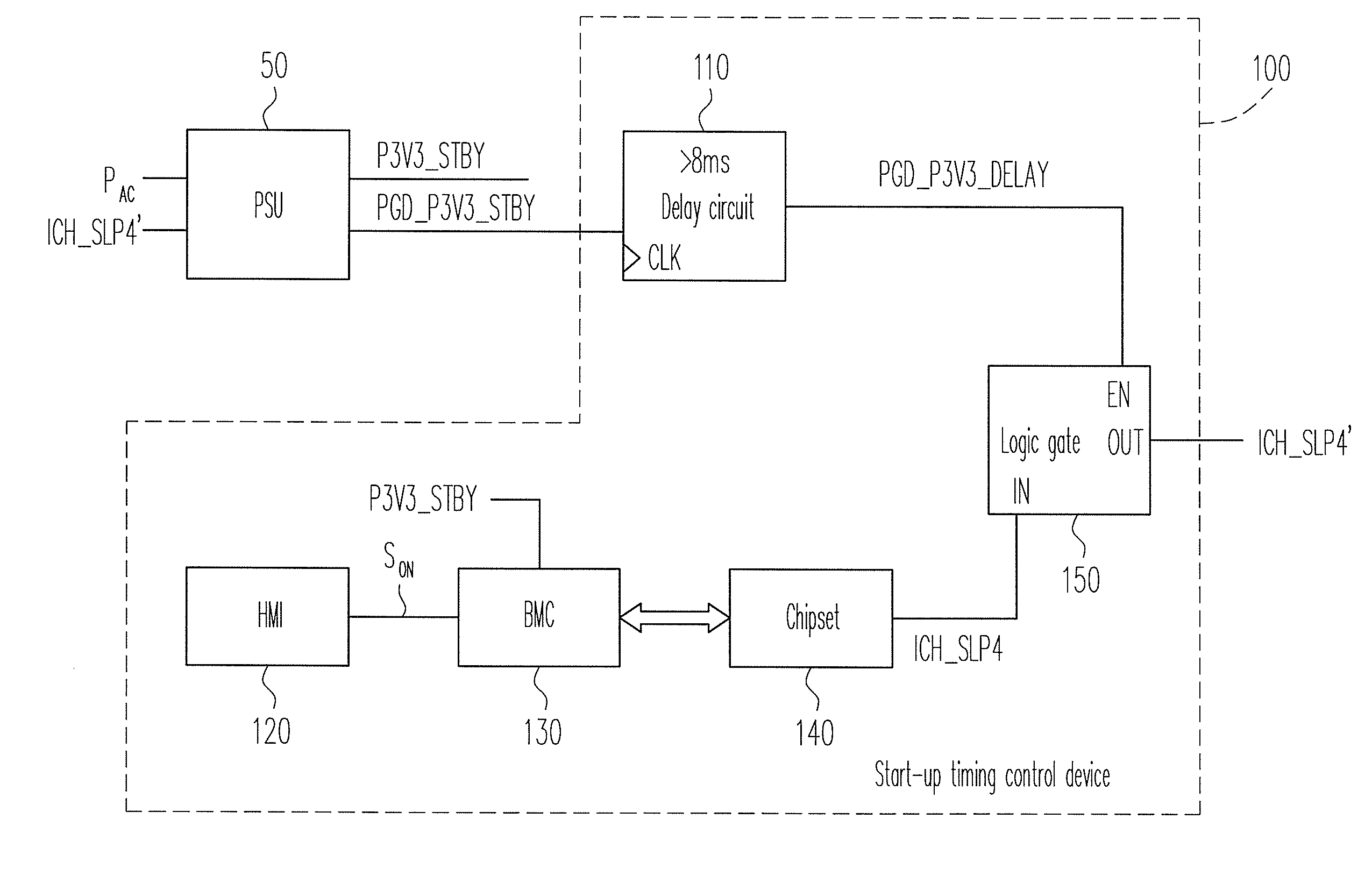
[0011]Accordingly, the present invention is directed to a computer start-up timing control device employing a delay circuit to delay a standby power ready signal generated by a power supply unit (PSU) of a computer platform. The delayed standby power ready signal is sent after a baseboard management controller (BMC) has finished initialization. Here, the delay standby power ready signal is used for controlling the transmission of a power supply signal to the PSU, so as to prevent other chipsets from accessing the BMC due to the start-up of the computer and obtaining erroneous information during the initialization of the BMC.

Problems solved by technology

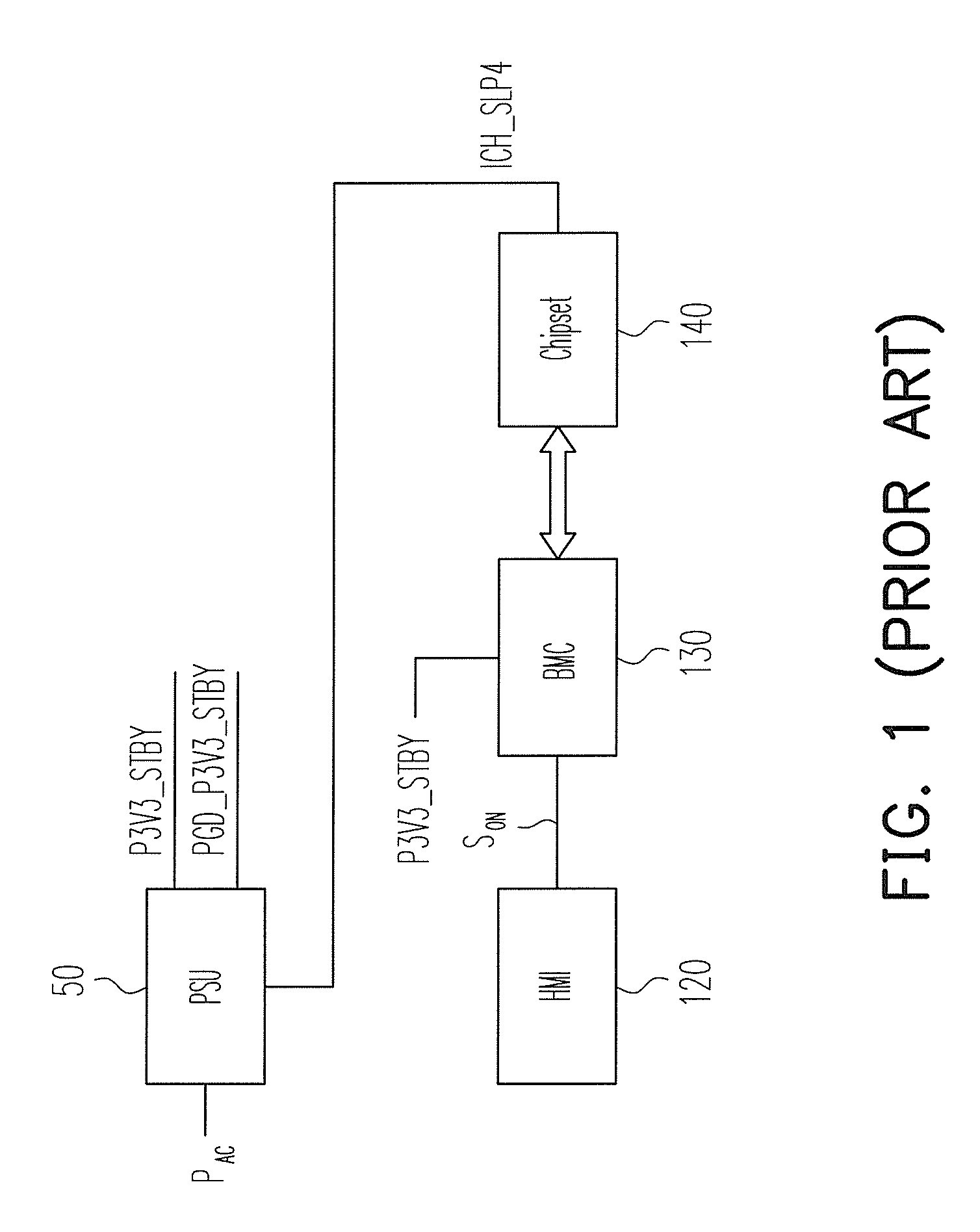
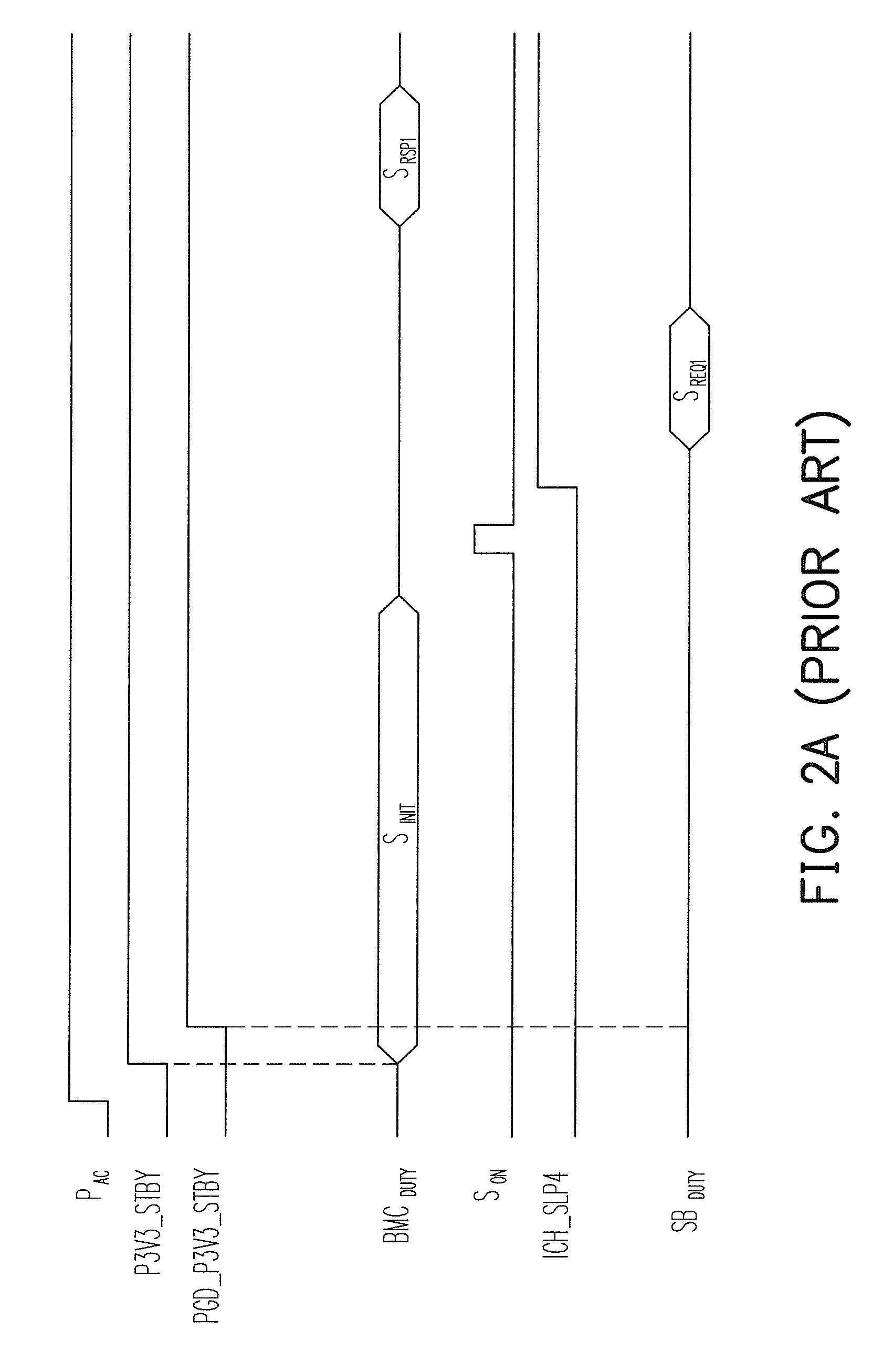
During the initialization of the BMC, if a user starts the computer, other chipsets will issue requests to the BMC upon functional requirements, and the BMC may feed back incorrect hardware information, such that unexpected errors may occur and cause potential problems in the system operation.
Referring to FIG. 2B, if the chipset 140 accesses the BMC 130 and requests for system information on the computer platform (in a period SREQ2 of the operating status SBDUTY) at this point, errors may occur in the information fed back to the chipset 140 because the BMC 130 has not yet finished the initialization (in a period SRSP2 of the operating status BMCDUTY), thus resulting in an unstable operation of the computer platform.

Method used


Image

  • Computer start-up timing control device and method thereof
  • Computer start-up timing control device and method thereof
  • Computer start-up timing control device and method thereof

Examples


Embodiment Construction

[0033]The features and effects of the start-up timing control device provided by the present invention are described in detail below in embodiments with the accompanying drawings.

[0034]Those of ordinary skill in the art should understand that, the start-up timing control in a computer involves the interaction of a plurality of hardware components. A computer start-up timing control device provided by the present invention utilizes a delay circuit to delay a standby power ready signal generated by a PSU of the computer platform and to send the delayed standby power ready signal after the BMC finishes initialization, so as to prevent the chipset from sending a power supply signal ahead of time. Thereby, unexpected system errors resulted from the obtaining of error information of other hardware components by accessing the BMC can be avoided. FIG. 3 is an architectural view of a computer start-up timing control device according to the present invention. The start-up timing control devic...


PUM


Abstract

A computer start-up timing control device and a method thereof are provided for generating a power supply signal to enable a power supply unit (PSU) to provide power. The device includes a chipset, a delay circuit, and a logic gate. The delay circuit delays a standby power ready signal of the computer to generate a standby power delay signal. The chipset generates a power supply signal. The standby power delay signal enables the logic gate to transmit the power supply signal to the PSU via the logic gate. The PSU provides a power to make the computer enter a start-up procedure. The standby power delay signal delays the time for the chipset to send a power supply signal, so that a baseboard management controller (BMC) has enough time to complete initialization. Therefore, the chipset is prevented from accessing the BMC and obtaining erroneous information before the BMC finishes initialization.

Description

CROSS-REFERENCE TO RELATED APPLICATION[0001]This application claims the priority benefit of China application serial no. 200810166532.7, filed Oct. 10, 2008. The entirety of the above-mentioned patent application is hereby incorporated by reference herein and made a part of specification.BACKGROUND OF THE INVENTION[0002]1. Field of the Invention[0003]The present invention generally relates to a computer, in particular, to a computer start-up timing control device and a method thereof.[0004]2. Description of Related Art[0005]On a conventional computer platform, chipsets are generally adopted to simplify the architecture of the computer hardware, and a number of integrated circuits (ICs) with different functions are integrated into individual chipsets. The chipsets are coupled with one another via buses for information transmission. In the past, a basic input output system (BIOS) is employed to manage the underlying information of a computer, and nowadays the chipsets are used to repl...

Claims


Application Information

Patent Timeline
IPC IPC(8): G06F1/00
CPCG06F1/26G06F1/24
Inventor HUANG, LANLIU, SHIH-HAO
Owner INVENTEC CORP
Learn More