Slot Rail Assembly

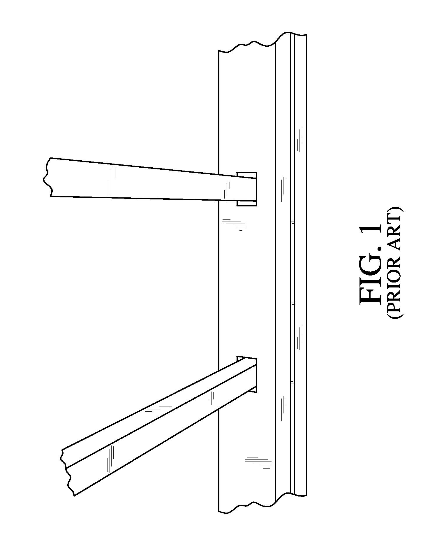
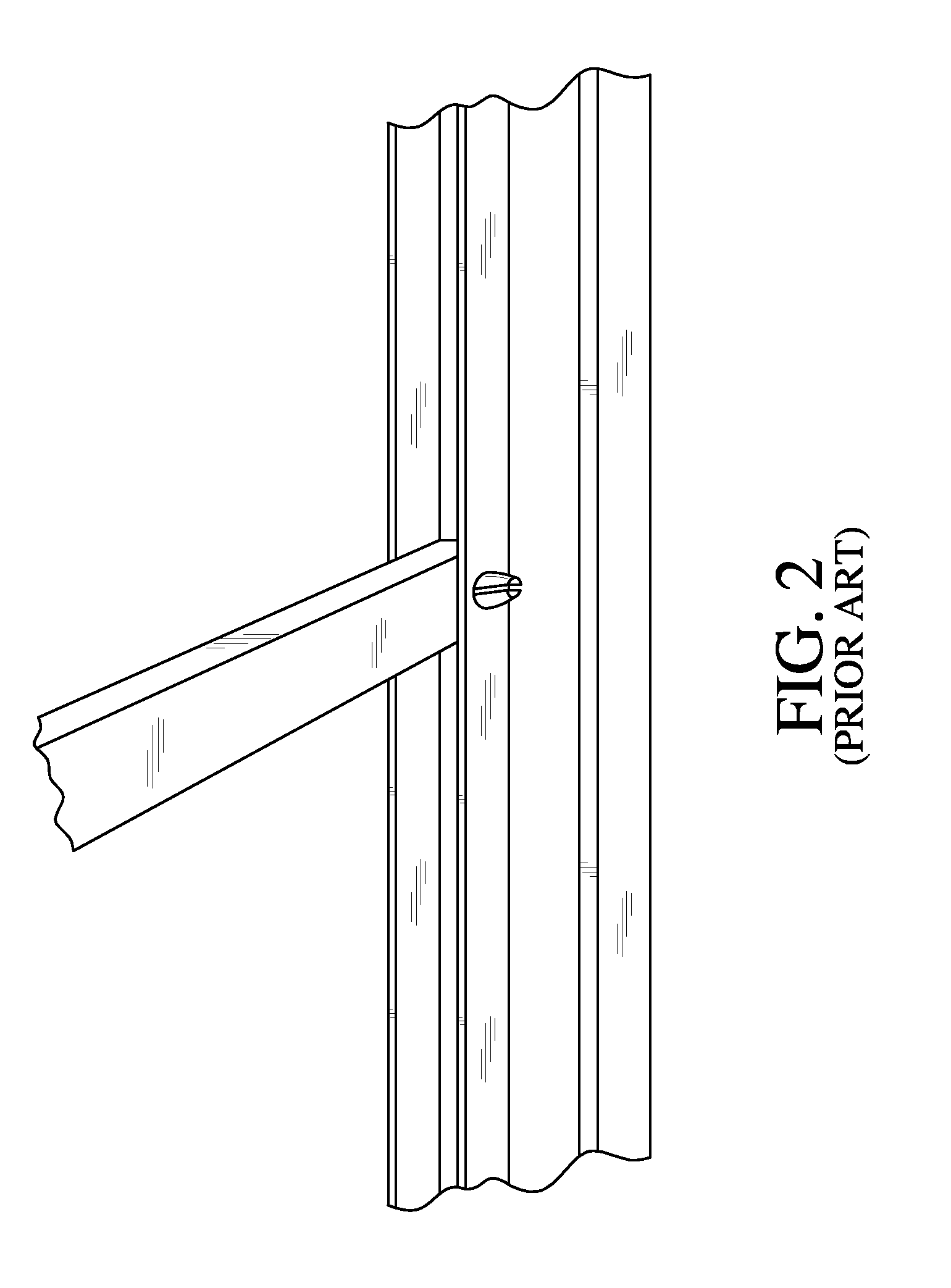
a technology for stair rails and assembly parts, which is applied in the direction of balustrades, fencing, buildings, etc., can solve the problems of difficult assembly, difficulty in properly positioning the balusters, and still requires a great deal of skill and car

Inactive Publication Date: 2009-07-16
KPB PROD L L C
View PDF29 Cites 29 Cited by
  • Summary
  • Abstract
  • Description
  • Claims
  • Application Information

AI Technical Summary

Benefits of technology

[0011]It is an object of the invention to provide an improved means for piv

Problems solved by technology

Most difficult is to properly position the balusters in precise vertically extending relation along the incline portion of the staircase once the rail portions have been cut and positioned between the posts.
However, since the assembly pivots together and is in

Method used


Image

  • Slot Rail Assembly
  • Slot Rail Assembly
  • Slot Rail Assembly

Examples


Embodiment Construction

—LISTING OF ELEMENTS

[0032]

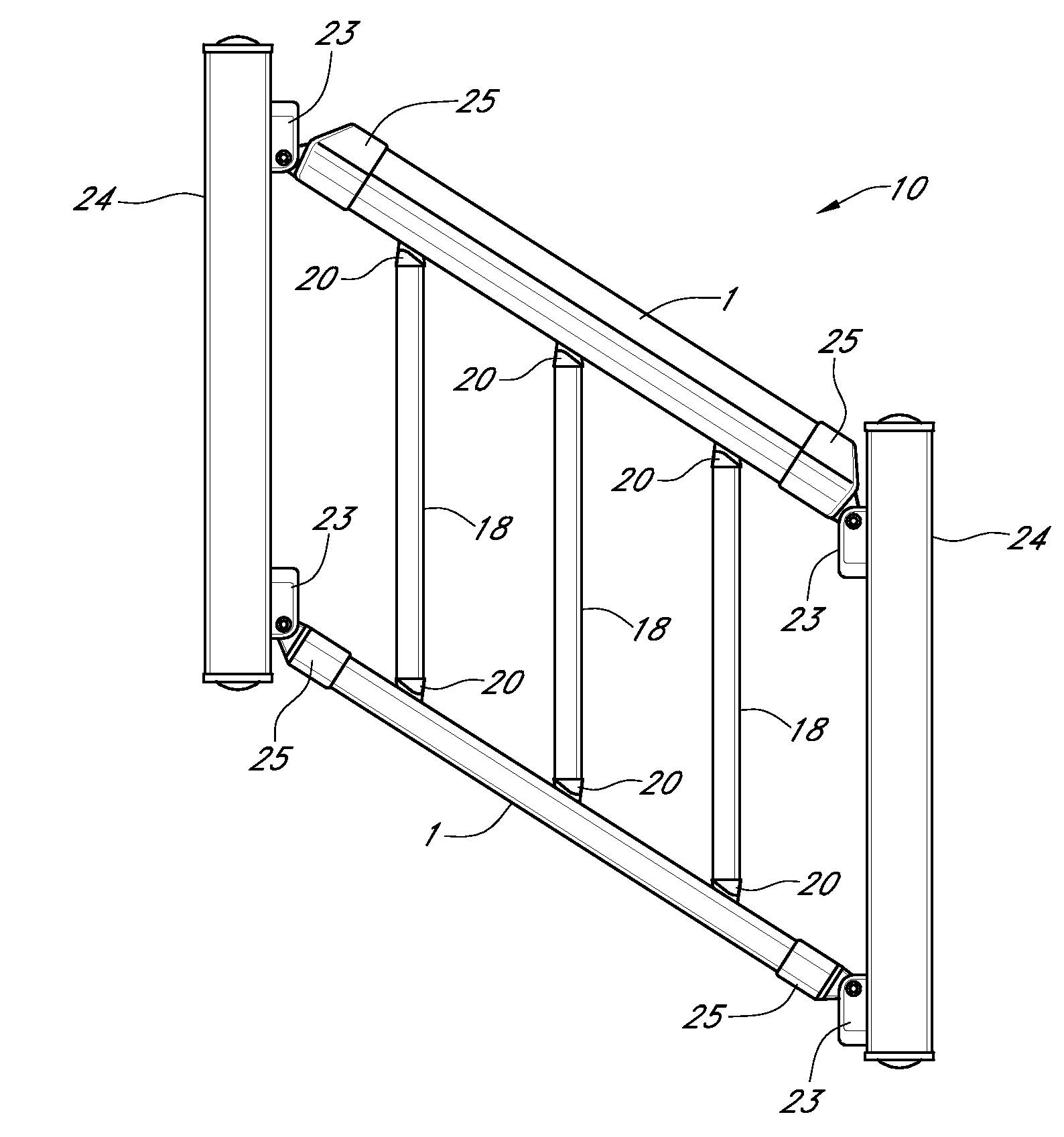
ELEMENT DESCRIPTIONELEMENT #Rail Portion1First Exterior Side Wall2Second Exterior Side Wall3Third Exterior Side Wall4Lateral Slot5First Interior Side Wall6Second Interior Side Wall7Third Interior Side Wall8Baluster Dowel9Slot Rail Assembly10First Locking Ledge11Second Locking Ledge12Lateral Shelf13First Support Shelf14Second Support Shelf15Spacer16Relative Angle17Baluster18Baluster Connector19Skirt portion20Connecting Portion21Supporting Portion22Hinge23End Post24Rail End Cap25Recess26Rail Interior27Projections28

DETAILED DESCRIPTION

[0033]Before the various embodiments of the present invention are explained in detail, it is to be understood that the invention is not limited in its application to the details of construction and the arrangements of components set forth in the following description or illustrated in the drawings. The invention is capable of other embodiments and of being practiced or of being carried out in various ways. Also, it is to be under...


PUM


Abstract

The slot rail assembly, in combination with a rail portion, at least one baluster, at least one baluster connector, and a lateral slot and at least one spacer is disclosed and claimed. The baluster may be slid distally along a lateral slot to accommodate the pitch or slope of incline or decline addressed. Lateral movement of the balusters within the lateral slot and change in relative angle of the baluster in relation to the rail portion allows the balusters to stay “plumb” no matter what the pitch of the stairs may be. At least one spacer may be snapped into place to fix the horizontal position of the balusters and to provide a seal against ingress of debris and moisture into the lateral slot. The slot rail assembly may be deployed as a stair rail, a stairway or an improved connection system for balusters and stair rails.

Description

CROSS REFERENCE TO RELATED APPLICATIONS[0001]The Applicant claims priority under 35 U.S.C. §119(e) of provisional U.S. patent application Ser. No. 61 / 011,304 filed on Jan. 16, 2008 which is incorporated by reference herein.FIELD OF INVENTION[0002]This invention relates generally to a stair rail system for stairs that includes a pivoting supporting device allowing for adjustment of the angle of the balusters and the like, and, more particularly, the stair rail system allows slideable adjustment of the variable angle balusters to used between the rail and a set of steps or between the hand and foot rails of a staircase assembly.STATEMENT REGARDING FEDERALLY SPONSORED RESEARCH OR DEVELOPMENT[0003]No federal funds were used to develop or create the invention disclosed and described in the patent application.REFERENCE TO SEQUENCE LISTING, A TABLE, OR A COMPUTER PROGRAM LISTING COMPACT DISK APPENDIX[0004]Not ApplicableAUTHORIZATION PURSUANT TO 37 C.F.R. §1.171(d)(c)[0005]A portion of the ...

Claims


Application Information

Patent Timeline
IPC IPC(8): E04F11/18
CPCE04F11/1834E04F2011/1827E04F2011/1821E04F2011/1823E04F11/1817E04F2011/1819
Inventor FERRIS, KENPURDY, BRYAN
Owner KPB PROD L L C
Why Eureka
Try Eureka