Flush mounting utility component assembly

a utility component and assembly technology, applied in the field of building construction, can solve the problems of inconvenient installation, damage to the occupant, and the functionality of the associated utility, and achieve the effect of convenient and quick installation, convenient installation and convenient us

Inactive Publication Date: 2017-03-28
FERRARA STEVE
View PDF16 Cites 14 Cited by
  • Summary
  • Abstract
  • Description
  • Claims
  • Application Information

AI Technical Summary

Benefits of technology

[0011]The invention is based at least in part on an understanding that there is a long unsatisfied need for improved configurations of utility component mounting assemblies and associated installation methods. Embodiments of the invention provide utility component mounting assemblies and elements thereof that are configured to mount substantially flush with wall material. Embodiments provide the advantage that existing building construction materials and techniques can be employed to mount the inventive utility component mounting assemblies such that there is little to no protrusion of the utility component mounting assemblies from installed wall material. Embodiments provide the advantage that installed utility component mounting assemblies can be finished with the same finish materials as are used with the wall material. Embodiments provide the advantage of substantially matching color and texture of finish material applied to embodiments of utility component mounting assemblies with adjacent wall material. Embodiments of utility component mounting assemblies and installation methods thereof result in a relatively unobtrusive contour and appearance that more fully blends in with the appearance of adjacent wall material to provide a more appealing appearance and more functional utility. Embodiments provide relatively inexpensive utility component mounting assemblies that can be readily and quickly installed in flexibly located mounting locations using installation methods that are readily understood and employ existing materials and skills.

Problems solved by technology

Placing wiring and cabling within the structure of the building isolates the wiring and cabling from undesired contact with occupants of the building which could damage the wiring and / or cabling and impair the functionality of the associated utility as well as potentially cause injury to the occupants.
However, these aspects of traditional utility components and their associated installation have undesired aspects in certain applications.
By protruding beyond the surface of a wall where it is mounted, a utility component is more subject to undesired contact with occupants and moving objects.
If unintended contact is forceful enough, damage to the utility component and / or injury to the occupant can occur.
Protruding utility components also pose the possibility of collision and damage with other appliances used in the building.
For example, a typical electrical outlet that is mounted relatively low on a building wall may be impacted by a vacuum cleaner used within the building causing disruption of the vacuuming operation and potentially incurring damage to the utility component and / or other appliance.

Method used


Image

  • Flush mounting utility component assembly
  • Flush mounting utility component assembly
  • Flush mounting utility component assembly

Examples


Embodiment Construction

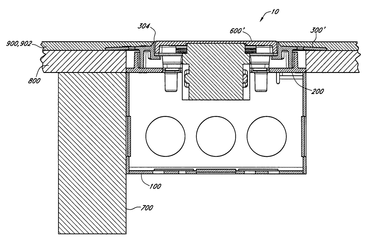
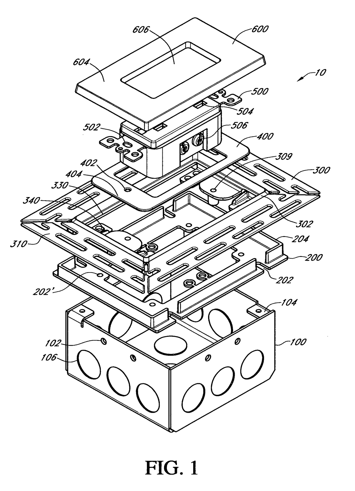
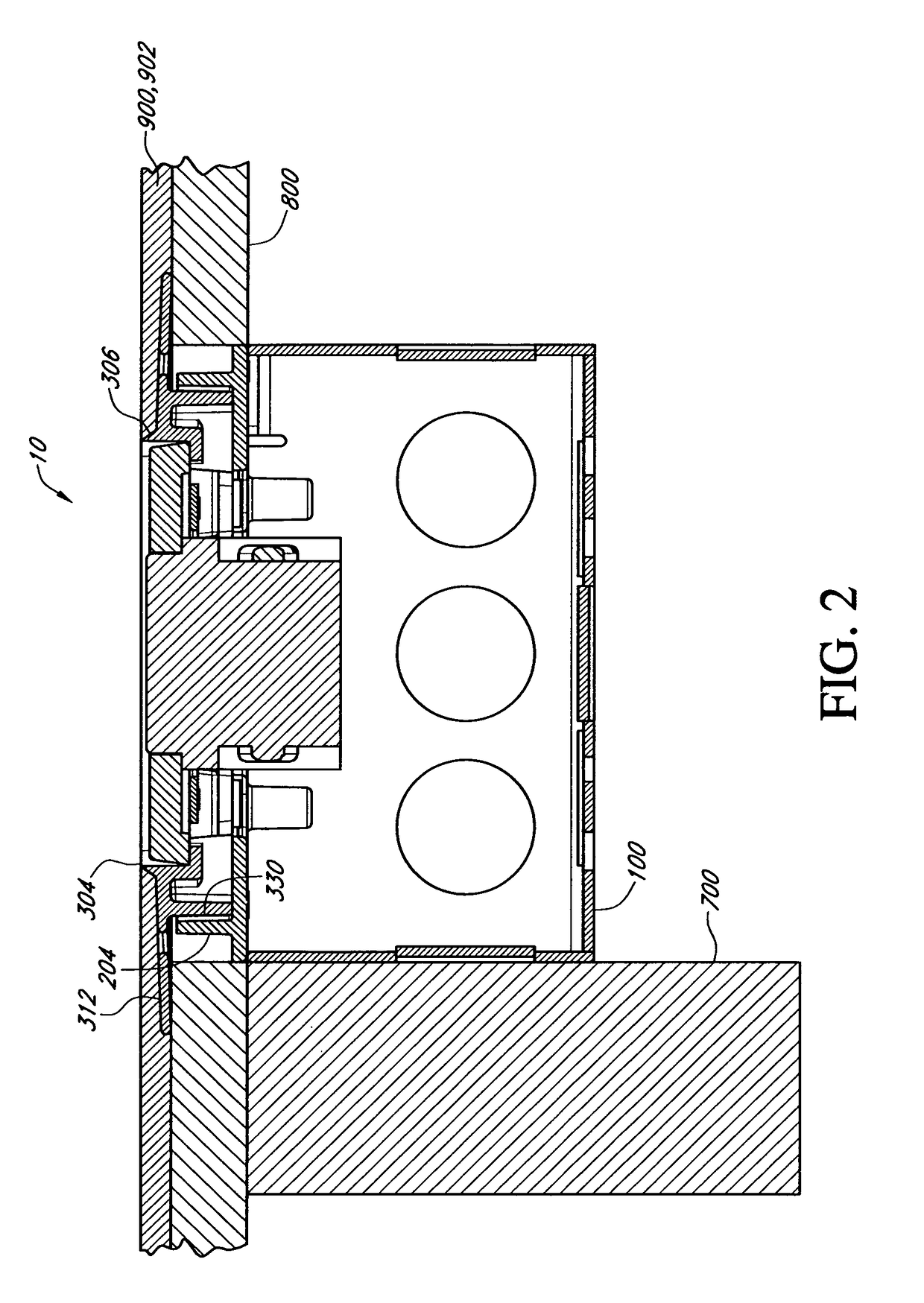
[0028]Reference will now be made to the drawings where like reference designators designate like parts throughout. FIG. 1 is an exploded perspective view of one embodiment of utility component mounting assembly 10. The utility component mounting assembly 10 is configured to provide an access connection for associated utility services and / or to provide control and / or monitoring functionality for associated utilities or appliances. Some non-limiting examples of the functions provided by the utility component mounting assembly 10 include, but are not limited to, one or more gangs of electrical receptacles, switches, regulators or dimmers, keypads, monitoring displays, telephone jacks, GFI outlets, coaxial cable connections, fiberoptic cable connections, Universal Serial Bus (USB) hubs, charging stations, volume controls, channel controls, wireless transceivers, motion sensors, speakers, microphones, light sensors, cameras, and the like. Detailed description will be provided for embodim...


PUM


Abstract

A utility component mounting assembly configured to be assembled and installed during building construction or remodeling and to provide access to a variety of residential, commercial, and / or industrial utilities in a manner that is unobtrusive and aesthetically appealing. In some aspects, the utility component mounting assembly is assembled and installed such that there is little or no outward protrusion of any portion of the assembly from a generally planar wall surface. The assembly provides the ability to apply the same final finishing materials to exposed portions of the assembly as to adjacent wall material. The assembly can be readily installed with existing building constructions materials, tools, and skills. The assembly can be mounted in flexible locations on a wall and in a vertical or horizontal orientation.

Description

RELATED APPLICATIONS[0001]This application is a continuation-in-part of U.S. Utility application Ser. No. 13 / 780,407 entitled “Flush Mounting Utility Component Assembly” filed Feb. 28, 2013 which claims the benefit of U.S. Provisional Application 61 / 618,816 filed Apr. 1, 2012 entitled “Flush Mount Box with Plaster Ring and Plate” and which is incorporated herein in its entirety by reference.BACKGROUND[0002]Field of the Invention[0003]This application relates to the field of building construction and to apparatus and methods for mounting one or more utility components in a low-profile or flush mounted configuration.[0004]Prior Art[0005]New building construction and / or remodeling typically includes providing utility components at various locations within the building. Utility components are frequently located at external surfaces of interior and / or exterior vertical walls. Utility components allow an owner / user of the building to access and utilize the associated utility and / or functi...

Claims


Application Information

Patent Timeline
Patent Type & Authority Patents(United States)
IPC IPC(8): H02B1/30H02G3/12H02G1/00H02G3/08H02B1/40H05K5/03
CPCH02G3/12H02G3/083H02G1/00H02G3/126H02G3/14
Inventor FERRARA, STEVE
Owner FERRARA STEVE
Why Eureka
Try Eureka