Radio frequency identification (RFID) method and apparatus for maximizing receive channel signal-to-noise ratio by adjusting phase to minimize noise

a radio frequency identification and phase adjustment technology, applied in the field of automatic data collection, can solve the problems of affecting the ability of rfid readers to accurately read rfid tags, adding to the baseband noise level, adversely affecting the reading performance of rfid readers, etc., to achieve the effect of minimizing noise and minimizing nois

Inactive Publication Date: 2009-07-16
INTERMEC IP
View PDF18 Cites 22 Cited by
  • Summary
  • Abstract
  • Description
  • Claims
  • Application Information

AI Technical Summary

Benefits of technology

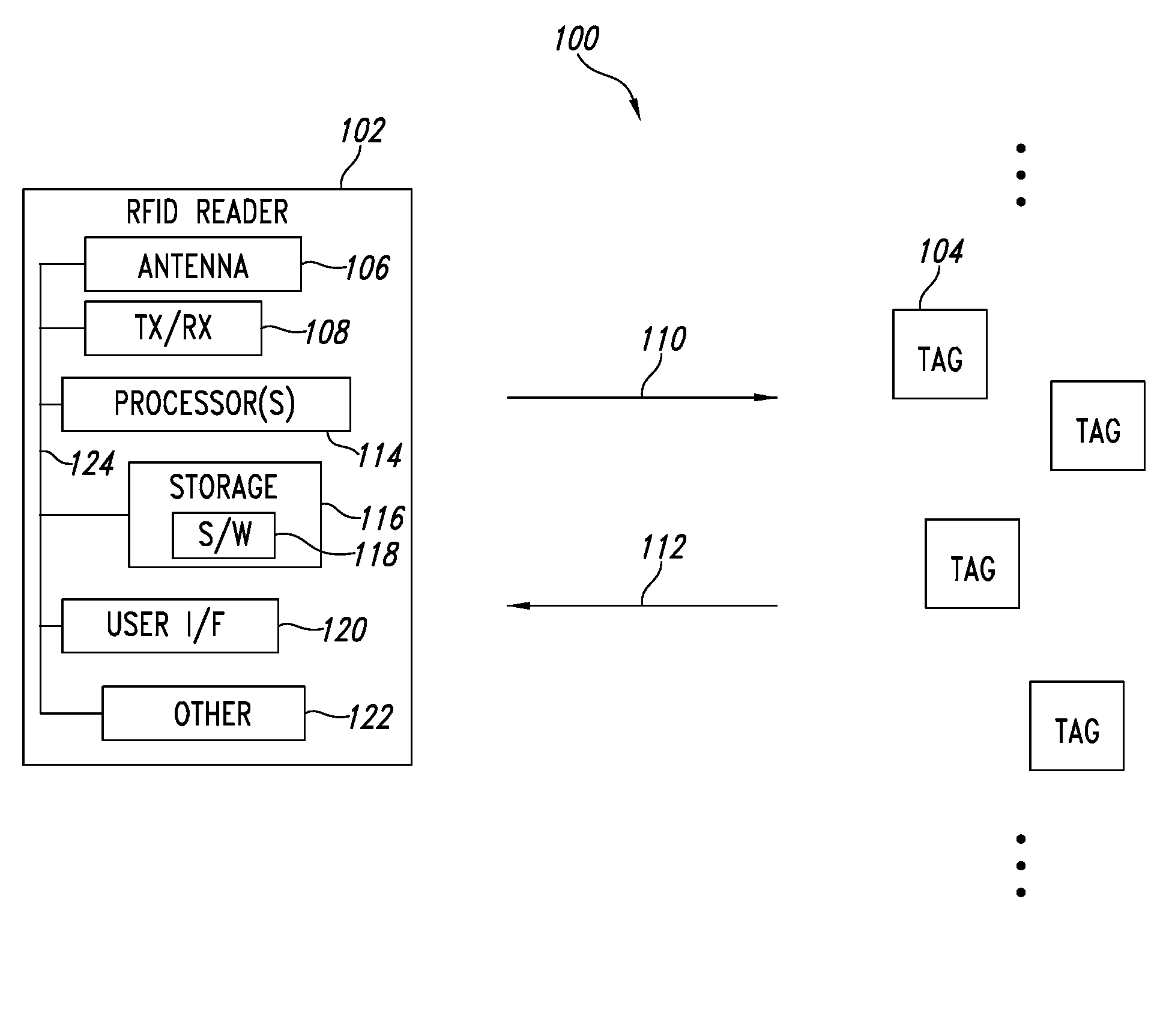
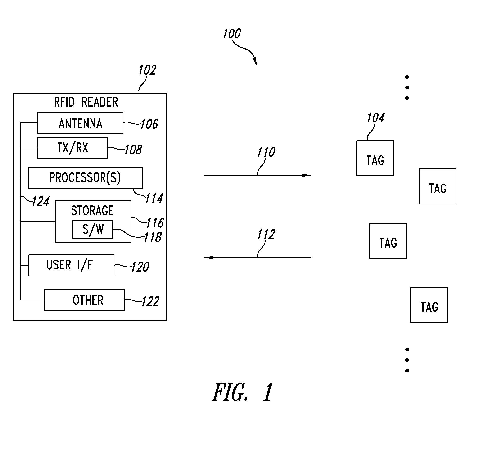
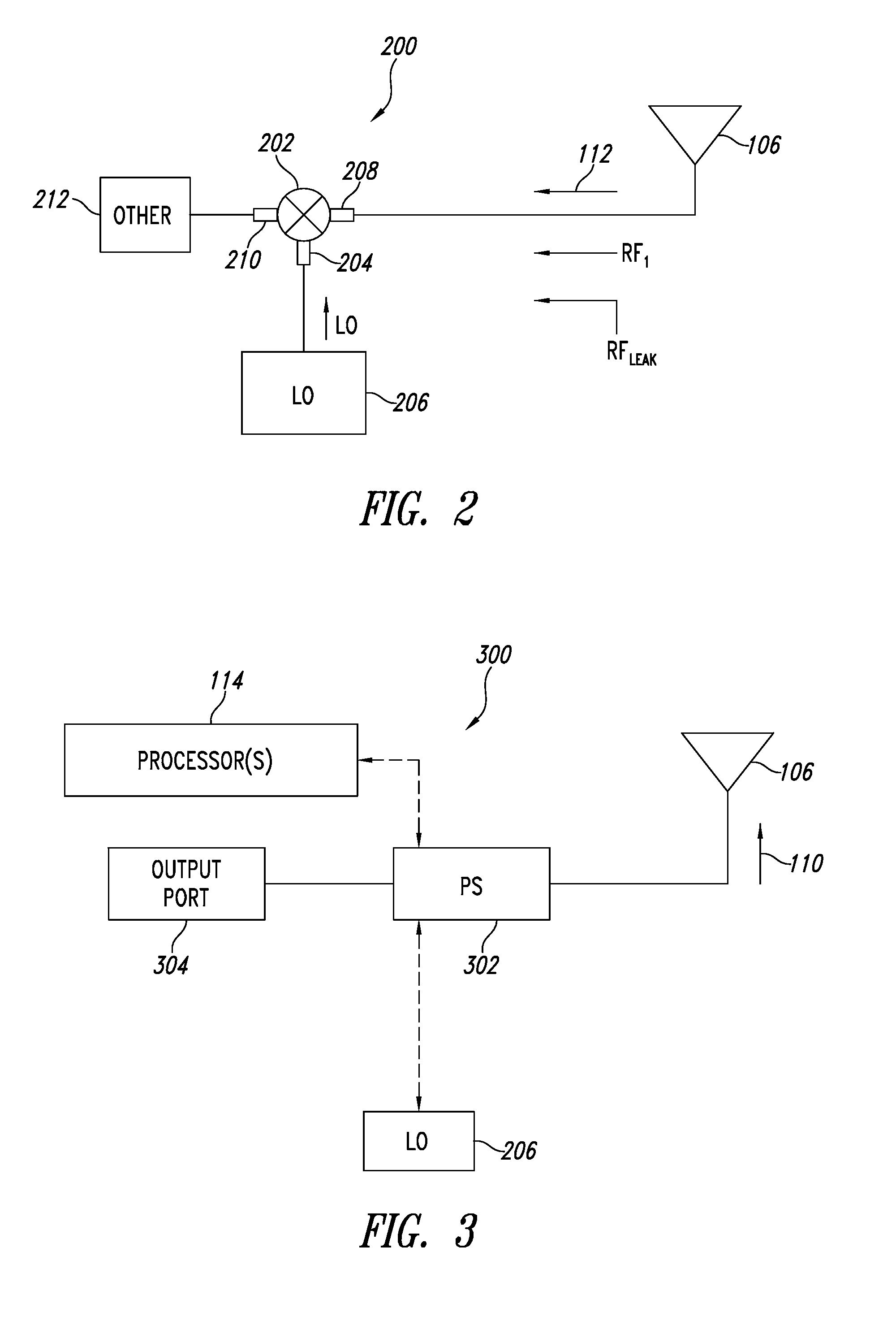
[0010]A radio frequency identification (RFID) reader apparatus may be summarized as including: at least one antenna for communicating with at least one RFID tag; phase shifting means for providing a phase shift to at least one signal present in a receive path downstream from the at least one antenna; and control means for controlling the phase shifting means to adjust a value of the phase shift to minimize noise, associated with the at least one signal, that is present in the rece...

Problems solved by technology

Noise often adversely affects the capability of an RFID reader to accurately read an RFID tag.
This large reflected signal...

Method used


Image

  • Radio frequency identification (RFID) method and apparatus for maximizing receive channel signal-to-noise ratio by adjusting phase to minimize noise
  • Radio frequency identification (RFID) method and apparatus for maximizing receive channel signal-to-noise ratio by adjusting phase to minimize noise
  • Radio frequency identification (RFID) method and apparatus for maximizing receive channel signal-to-noise ratio by adjusting phase to minimize noise

Examples


Embodiment Construction

[0019]In the following description, numerous specific details are given to provide a thorough understanding of embodiments. The embodiments can be practiced without one or more of the specific details, or with other methods, components, materials, etc. In other instances, well-known structures, materials, or operations associated with RFID tags and RFID readers, computer and / or telecommunications networks, and / or computing systems are not shown or described in detail to avoid obscuring aspects of the embodiments.

[0020]Unless the context requires otherwise, throughout the specification and claims which follow, the word “comprise” and variations thereof, such as, “comprises” and “comprising” are to be construed in an open, inclusive sense, that is as “including, but not limited to.”

[0021]Reference throughout this specification to “one embodiment” or “an embodiment” means that a particular feature, structure, or characteristic described in connection with the embodiment is included in ...


PUM


Abstract

Noise in a receive path of a radio frequency identification (RFID) reader is reduced by using a phase shifter. By reducing the noise, the signal-to-noise ratio (SNR) in the receive path of the RFID reader is improved, thereby increasing the number of RFID tags that can be read in a noisy environment over time and/or improving the capability to distinguish a return signal of the RFID tag(s) from noise. The phase shifter adds a phase shift to a reflected signal and a leakage signal, or to a local oscillation signal.

Description

CROSS REFERENCE TO RELATED APPLICATIONS[0001]This application claims benefit under 35 U.S.C. 119(e) to U.S. provisional patent application Ser. No. 61 / 020303, filed Jan. 10, 2008, which is incorporated herein by reference in its entirety.TECHNICAL FIELD[0002]This disclosure generally relates to the field of automatic data collection (ADC), for example, data acquisition via radio frequency identification (RFID) tags. More particularly but not exclusively, the present disclosure relates to improving the reading of RFID tags by an RFID reader in a noisy environment.BACKGROUND INFORMATION[0003]The ADC field includes a variety of different types of ADC data carriers and ADC readers operable to read data encoded in such data carriers. For example, data may be encoded in machine-readable symbols, such as barcode symbols, area or matrix code symbols, and / or stack code symbols. Machine-readable symbols readers may employ a scanner and / or imager to capture the data encoded in the optical patt...

Claims


Application Information

Patent Timeline
IPC IPC(8): H04Q5/22
CPCH04B5/0062H04Q2213/13098H04Q2213/13095
Inventor PILLAI, VIJAYPETERNEL, JAMES R.
Owner INTERMEC IP
Why Eureka
Try Eureka