Liquid ejection head

a liquid ejection head and liquid ejection technology, applied in the direction of printing, inking apparatus, etc., can solve the problems of reducing the price of the ink jet recording apparatus, electrical connection failure, liquid (ink) leakage from the liquid supply passage, etc., to improve adhesive reliability and reduce production costs.

Inactive Publication Date: 2009-07-16
CANON KK
View PDF10 Cites 13 Cited by
  • Summary
  • Abstract
  • Description
  • Claims
  • Application Information

AI Technical Summary

Benefits of technology

[0014]A principal object of the present invention is to provide a liquid ejection head capable of improving adhesive reliability thereof with a supporting member for a liquid ejection substrate, reliability of electric wiring protection from liquid, and a liquid supply performance and capable of reducing a production cost.
[0015]Another object of the present invention is to provide a liquid ejection head capable of realizing connection with very high reliability with respect to ink leakage, corrosion of an electrical connecting portion, and the like when the liquid ejection substrate is adhesively fixed and disposed on the supporting member.

Problems solved by technology

In recent years, a lowering in price of an ink jet recording apparatus is noticeable, so that there arises a problem of how to prepare an ink jet head inexpensively.
However, when a constitution in which the liquid ejection substrate is elongated and narrowed is employed, the above-described ink jet head has been accompanied with the following problems such that it causes leakage of the liquid (ink) from the liquid supply passages or electrical connection failure due to corrosion of an electrical connecting portion.
On the other hand, in the case where the supporting member 10 is a burned product of a ceramic material, due to contraction of the burned product during burning, it is difficult to ensure flatness of an adhesive surface for adhering the liquid ejection substrate 100, so that the burned product is generally surface-polished for use after the burning.
Therefore, there is a possibility that adhesive reliability of this portion is lowered.
Accordingly, it is necessary to completely isolate the electrical connecting member from liquid for ejection, but it is very difficult to ensure an adhesive sealing area.

Method used


Image

  • Liquid ejection head
  • Liquid ejection head
  • Liquid ejection head

Examples


embodiment 1

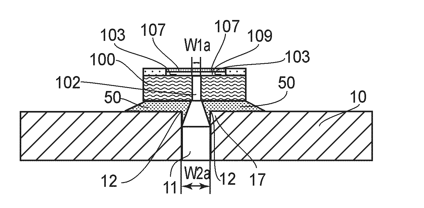
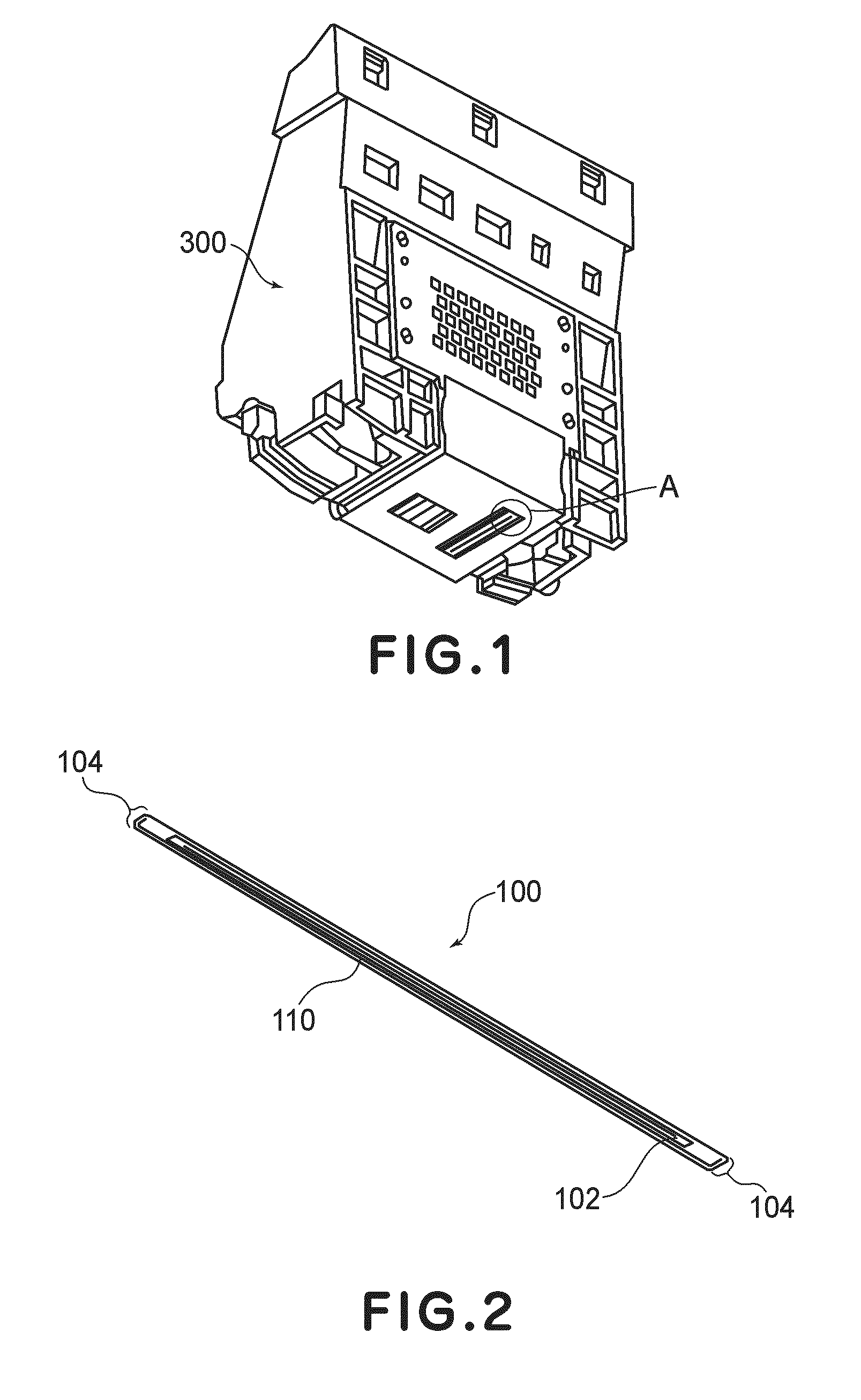
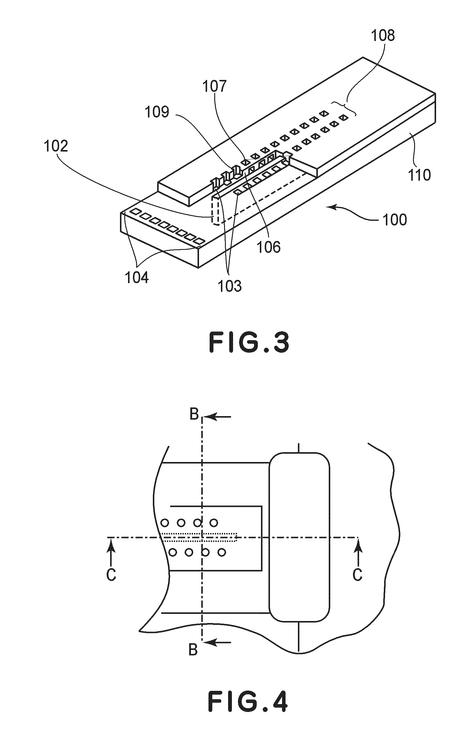
[0045]FIG. 1 is a perspective view of an outer appearance of an ink jet head according to Embodiment 1 of the present invention. FIG. 2 is a schematic perspective view of a liquid ejection substrate used in the ink jet head shown in FIG. 1. FIG. 3 is a partly enlarged perspective view of the liquid ejection substrate shown in FIG. 2. FIG. 4 is an enlarged schematic view of portion A in FIG. 1. FIGS. 5A and 5B are schematic views each showing a cross-section of a supporting member in the neighborhood of a liquid supply hole for supplying a recording liquid as an example of liquid to be supplied to a liquid ejection substrate, wherein FIG. 5A is a sectional view taken along B-B line in FIG. 4 and FIG. 5B is a sectional view taken along C-C line in FIG. 4.

[0046]The ink jet head according to this embodiment includes, as shown in FIGS. 1-5, a supporting member 10 and a liquid ejection substrate 100 mounted on the supporting member 10. Further, a recording liquid supply member 300 is conn...

embodiment 2

[0055]FIG. 7 is a perspective view of an outer appearance of an ink jet head according to Embodiment 2 of the present invention. FIG. 8 is a perspective view of an outer appearance of a three-dimensionally wired supporting member (a supporting member prepared by laminating ceramic sheets and forming electric wiring three-dimensionally in the ceramic sheets) shown in FIG. 7. FIG. 9 is a schematic plan view of an outer appearance showing a state in which the liquid ejection substrate of FIG. 2 is mounted on is the three-dimensionally wired supporting member of FIG. 8. FIG. 10 is a schematic sectional view, of the three-dimensionally wired supporting member in the neighborhood of an electrode for supplying driving electric power to the liquid ejection substrate, taken along D-D line in FIG. 9. FIG. 11A is a schematic sectional view taken along E-E line in FIG. 9. FIG. 11B is a schematic sectional view, of the three-dimensionally wired supporting member in the neighborhood of the liquid...

embodiment 3

[0072]FIGS. 15 to 20 are schematic views each for illustrating an ink jet head in Embodiment 3 according is to the present invention, wherein FIGS. 15A, 15B, 16, 17A, 17B, 18, 20A and 20B are sectional views showing a portion in the neighborhood of a liquid supply port for supplying a recording liquid to a liquid ejection substrate 100 and FIG. 19 is a plan view thereof.

[0073]In Embodiment 2 described above, the liquid supply hole 207 of the supporting member is increased in hole width compared with the liquid supply port 102 of the liquid ejection substrate 100. Further, the uppermost layer of the supporting member 200, i.e., the inner wall surface of the liquid supply hole 207 containing the edge line portion of the liquid supply hole 207 with respect to the supporting surface for the liquid ejection substrate 100 is covered with the sealant 206. These constitutions are similarly employed in this embodiment. However, in this embodiment, hole widths of the liquid supply hole 207 of...


PUM


Abstract

A liquid ejection head is constituted by a liquid ejection substrate comprising a liquid supply port for supplying liquid, an ejection outlet for ejecting the liquid supplied from the liquid supply port, and ejection energy generating devices for generating energy for ejecting the liquid; and a supporting member having a supporting surface for supporting the liquid ejection substrate and a liquid supply hole for supplying liquid to the liquid ejection substrate, the liquid supply hole communicating with the liquid supply port of the liquid ejection substrate to form a communicating portion, a periphery of which is sealed by a sealant. The liquid supply hole of the supporting member has an opening larger than that of the liquid supply port of the liquid ejection substrate. The support member has an inner wall portion including an edge line portion defined by the liquid supply hole on a side where the liquid ejection substrate is to be disposed. The inner wall portion is covered with the sealant.

Description

FIELD OF THE INVENTION AND RELATED ART[0001]The present invention relates to a liquid ejection head for ejecting liquid from an ejection outlet.[0002]As a liquid ejection head, an ink jet head for ejecting ink droplets by utilizing energy generating by an electrothermal transducer element has been known.[0003]In the ink jet head of this type, as shown in FIGS. 22 and 23, a silicon-made liquid ejection substrate 100 is mounted on a supporting member 10 formed of a resin material or a ceramic material to be integrated. The liquid ejection substrate 100 includes ejection outlets 107 through which ink droplets are to be ejected, liquid chambers 109 for temporarily retaining the ink droplets (ink) ejected from the ejection outlets 107, liquid supply ports 102 communicating with the liquid chambers 109, and electrothermal transducer elements 103 for supplying ejection energy to the ink in the liquid chambers 109.[0004]More specifically, a back surface of the liquid ejection substrate 100 ...

Claims


Application Information

Patent Timeline
Patent Type & Authority Applications(United States)
IPC IPC(8): B41J2/14B41J2/04
CPCB41J2/14024B41J2/14072B41J2202/18B41J2202/11B41J2/14145
Inventor HIROSAWA, TOSHIAKIIWANAGA, SHUZO
Owner CANON KK
Why Eureka
Try Eureka