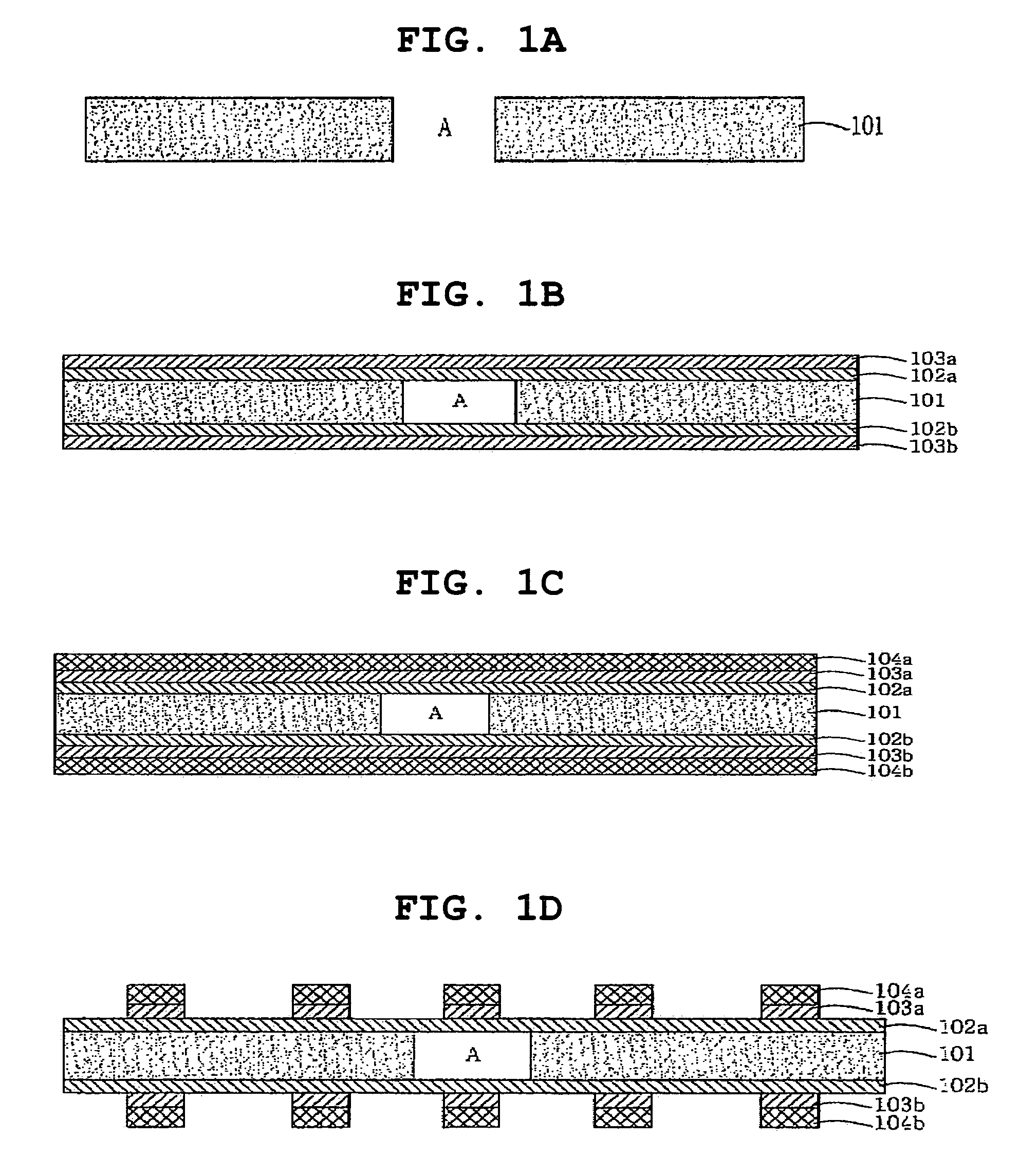
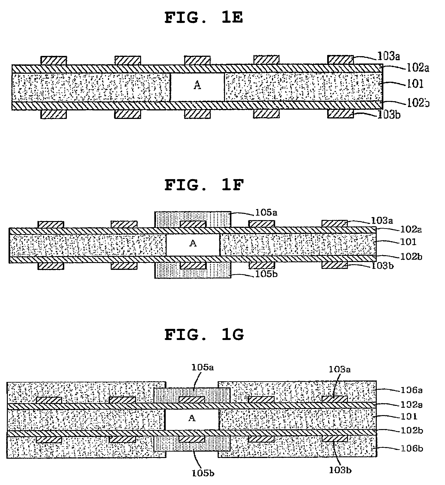
Rigid flexible printed circuit board and method of fabricating same

a printed circuit board and rigid technology, applied in the direction of resistive material coating, superimposed coating process, liquid/solution decomposition chemical coating, etc., can solve the problems of flexible pcb reducing workability in the production process, complex process of fabricating multi-layered flexible pcb, and high cost and defective fractions, so as to achieve excellent adhesion. , the effect of good adhesion

Inactive Publication Date: 2008-03-25
SAMSUNG ELECTRO MECHANICS CO LTD
View PDF6 Cites 14 Cited by
  • Summary
  • Abstract
  • Description
  • Claims
  • Application Information

AI Technical Summary

Benefits of technology

[0022]Accordingly, the present invention has been made keeping in mind the above problems occurring in the prior art, and an object of the present invention is to provide a low-priced rigid flexible PCB having no polyimide copper clad laminate, in which the reliability of adhesion is excellent, bendability is realized, and there are no bursts in a bent portion, and a method of fabricating the same.

Problems solved by technology

However, a process of fabricating the multilayered flexible PCB is complicated and has many stages compared to a process of fabricating a general rigid PCB, thus costs and defective fractions are high.
The flexible portion of the rigid flexible PCB reduces workability in a process of producing goods and increases defective fractions.
Polyimide resin has mainly been used as the material because there is no material usable as a substitute for polyimide resin with regard to heat resistance, mechanical strength, fire retardancy, and electrical properties.
However, currently, material capable of being used as a substitute for polyimide resin has been developed with regard to high frequency response, moisture resistance, dimensional stability, and cost.
However, since costly flexible polyimide copper clad laminate is employed, the fabrication cost is 3-4 times as high as that of a typical rigid flexible PCB.
As well, poor adhesion strength at an interface of the prepreg (or bonding sheet), which is used as an interlayer adhesive to form multilayered rigid portions, and polyimide has been indicated as a disadvantage in the fabrication of the PCB and in the realization of reliability for a long time.
However, in the conventional PCB, a polyimide copper clad laminate and a prepreg made of different materials constitute a rigid region, thus adhesion strength is reduced.
Additionally, in the conventional PCB, since a coverlay is laminated on the polyimide copper clad laminate on which a circuit pattern is formed, the circuit pattern is curled toward a curved portion of the coverlay due to coefficient of thermal expansion (CTE) of adhesive of the coverlay when thermal hysteresis occurs (surface mount process, etc.), thus mounting of surface mount devices is unsatisfactorily conducted, resulting in increased defective fractions.
Another problem is that, since cost of the polyimide copper clad laminate is higher than that of the prepreg, it is impossible to form a low-priced rigid flexible copper clad laminate.

Method used


Image

  • Rigid flexible printed circuit board and method of fabricating same
  • Rigid flexible printed circuit board and method of fabricating same
  • Rigid flexible printed circuit board and method of fabricating same

Examples


Embodiment Construction

[0043]Hereinafter, a detailed description will be given of a rigid flexible PCB, which does not comprise a polyimide copper clad laminate, and a method of fabricating the same according to the present invention, referring to the accompanying drawings.

[0044]FIGS. 2A to 3K show the fabrication of a six-layered rigid flexible PCB through single-side lamination.

[0045]FIGS. 2A to 2R are sectional views illustrating the fabrication of a rigid flexible PCB, according to an embodiment of the present invention.

[0046]As shown in FIG. 2A, a window (C) is formed through a first prepreg 201. The window (C) may be formed through the first prepreg 201 using a punch or a drill bit. The window (C) constitutes a flexible portion of a final product.

[0047]In FIG. 2B, a copper foil 202 is applied on an upper side of the first prepreg 201, and a protective film, such as a first coverlay 203b, is applied on a lower side of the first prepreg so as to cover the window (C). Subsequently, pressing is conducte...


PUM

PropertyMeasurementUnit
thicknessaaaaaaaaaa
thicknessaaaaaaaaaa
thicknessaaaaaaaaaa

Abstract

A rigid flexible printed circuit board (PCB) and a method of fabricating the same. Since a polyimide copper clad laminate is not used during the fabrication of the rigid flexible PCB, an increase in cost resulting from use of the polyimide copper clad laminate and poor reliability of adhesion at an interface between different materials are avoided.

Description

INCORPORATION BY REFERENCE[0001]The present application claims priority under 35 U.S.C. §119 to Korean Patent Application Nos. 10-2005-0016044 filed on Feb. 25, 2005 and 10-2005-0055647 filed on Jun. 27, 2005. The content of the applications is incorporated herein by reference in its entirety.BACKGROUND OF THE INVENTION[0002]1. Field of the Invention[0003]The present invention relates, in general, to a rigid flexible printed circuit board (PCB) and a method of fabricating the same and, more particularly, to a rigid flexible PCB and a method of fabricating the same, in which a polyimide copper clad laminate is not used during the fabrication of the rigid flexible PCB so as to avoid an increase in cost resulting from use of the polyimide copper clad laminate and poor reliability of adhesion at an interface between different materials.[0004]2. Description of the Related Art[0005]In accordance with the recent trend toward miniaturized, light, and slim electronic devices, light, slim, an...

Claims


Application Information

Patent Timeline
Patent Type & Authority Patents(United States)
IPC IPC(8): H01B13/00H05K3/02H05K3/10
CPCC23C26/00C23C28/00H05K3/4691C23C28/023H05K3/4652H05K2201/0187Y10T29/49155H05K2201/0382H05K2201/09109H05K2203/063H05K2201/0355
Inventor MYUNG, BUM YOUNGKIM, DONG KUKPARK, YOUNG POYOON, YOUNG SEOKYANG, DEK GIN
Owner SAMSUNG ELECTRO MECHANICS CO LTD
Why Eureka
Try Eureka