Combining reservoir modeling with downhole sensors and inductive coupling

a reservoir and sensor technology, applied in the field of well characterization, can solve the problems of equipment tendencies and inaccurate indications, and achieve the effect of improving wellbore or reservoir modeling

Active Publication Date: 2009-07-16
SCHLUMBERGER TECH CORP
View PDF40 Cites 24 Cited by
  • Summary
  • Abstract
  • Description
  • Claims
  • Application Information

AI Technical Summary

Benefits of technology

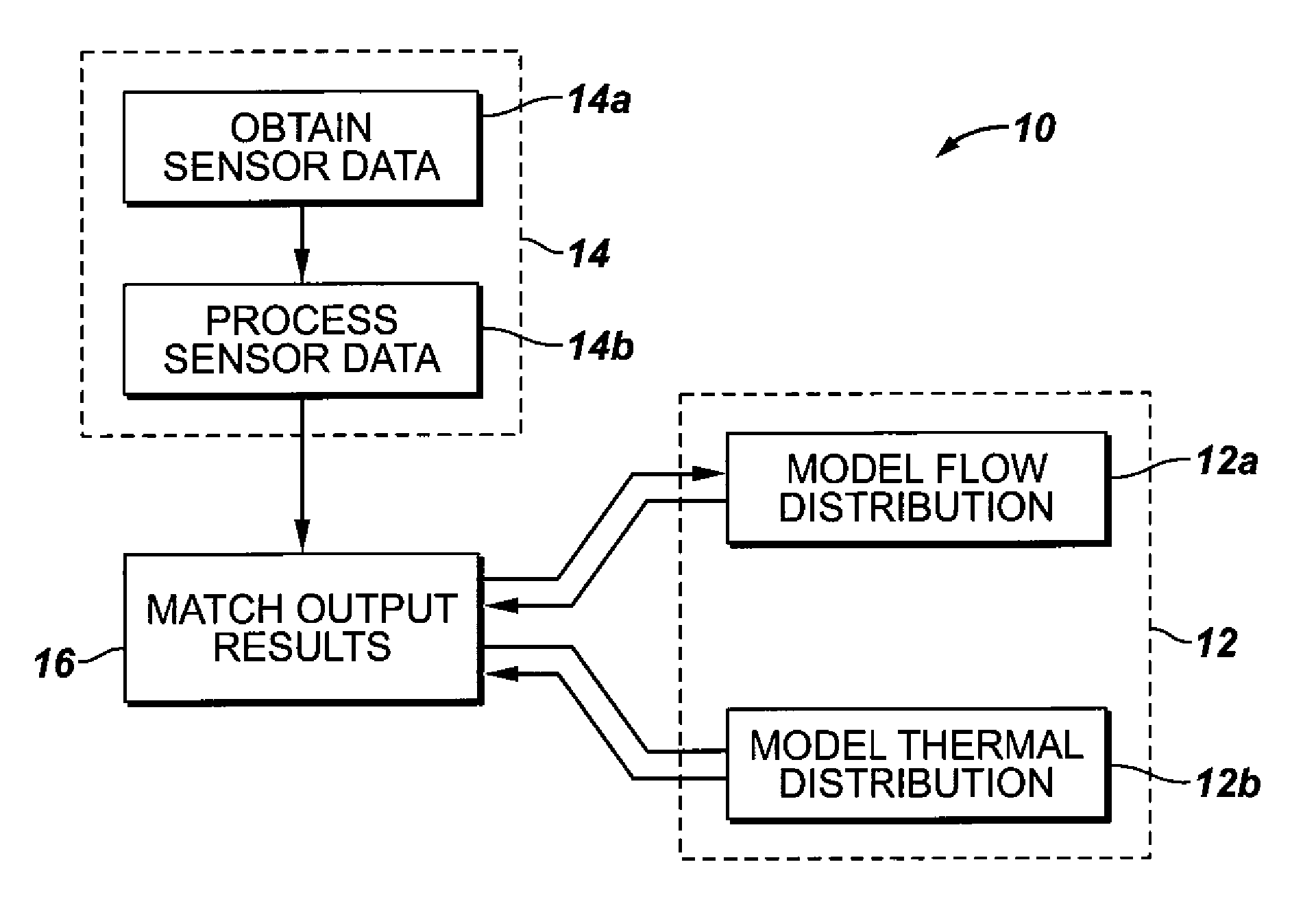
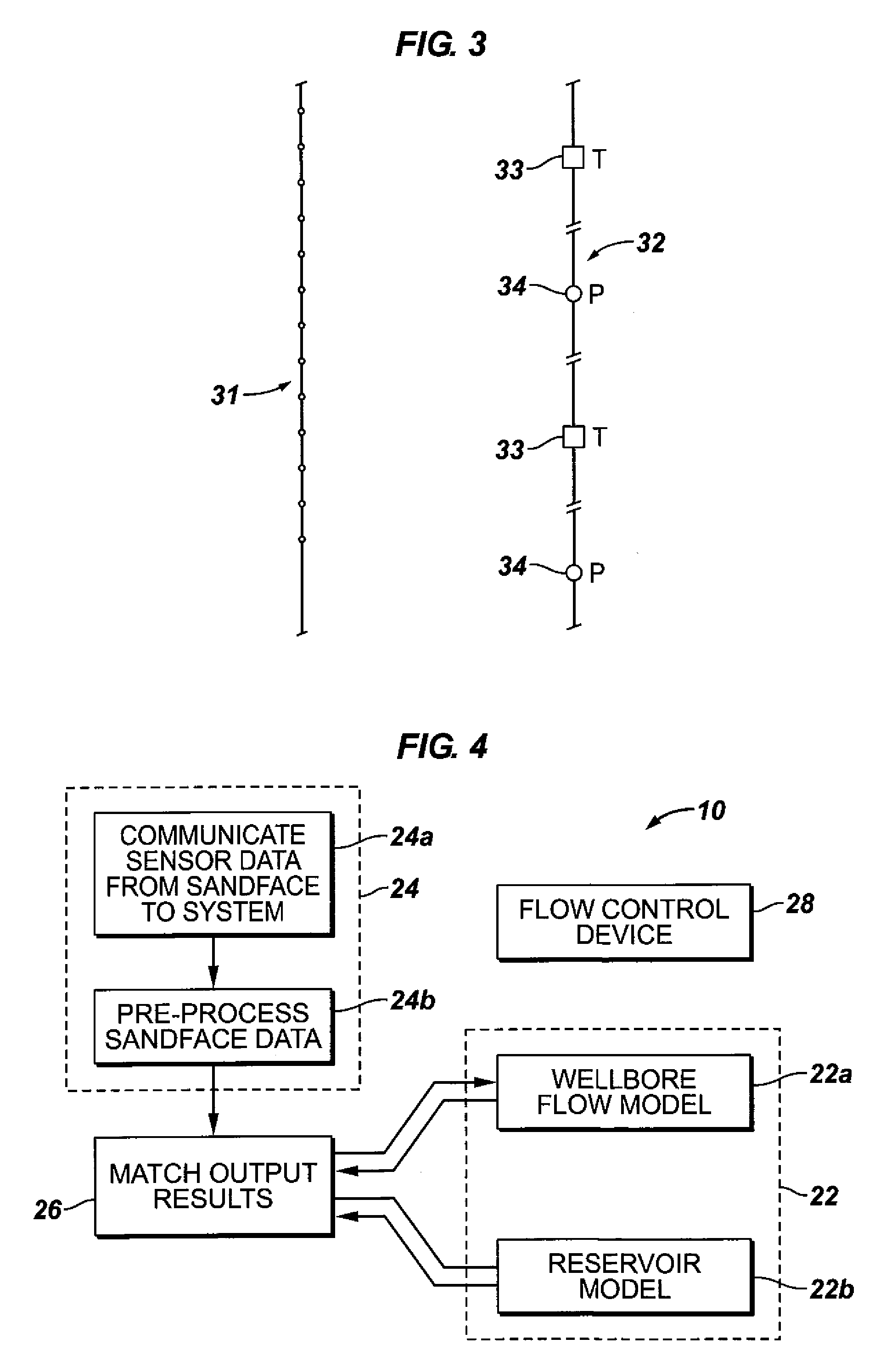
[0014]The measured data may also be used to further enhance the wellbore or reservoir modeling. For example, given a series of different flow rates in a wellbore, an optimal match between

Problems solved by technology

A drawback to the use of monitoring equipment is that the equipment tends to provide an indication of the abnormal condition once the event has already occurred.
This type of monitoring equipment only

Method used


Image

  • Combining reservoir modeling with downhole sensors and inductive coupling
  • Combining reservoir modeling with downhole sensors and inductive coupling
  • Combining reservoir modeling with downhole sensors and inductive coupling

Examples


Embodiment Construction

[0020]It will be appreciated that the present invention may take many forms and embodiments. In the following description, some embodiments of the invention are described and numerous details are set forth to provide an understanding of the present invention. Those skilled in the art will appreciate, however, that the present invention may be practiced without those details and that numerous variations of and modifications from the described embodiments may be possible. The following description is thus intended to illustrate and not to limit the present invention.

[0021]As used here, the terms “up” and “down”; “upper” and “lower”; “upwardly” and “downwardly”; “below” and “above”; and other similar terms indicating relative positions above or below a given point or element may be used in connection with some implementations of various technologies described herein. However, when applied to equipment and methods for use in wells that are deviated or horizontal, or when applied to equi...


PUM


Abstract

A method is disclosed of characterizing a well using a series of measurements taken along the sandface of that well in order to optimize a well model. The method may comprise providing a well model with a plurality of adjustable physical parameters, providing a data set made up of a plurality of sandface measurements, and running the well model with different combinations of adjustable physical parameters so that the results of the well model substantially match the results of the sandface measurements. In one embodiment, the method may comprise creating a communication pathway between the surface and the sandface including an inductive coupler. A further step may include pre-processing the plurality of the sandface measurements. In addition, a further step may be to establish or set at least one control device in order to change the flow characteristics of the production fluid in the well.

Description

CROSS-REFERENCE TO RELATED APPLICATION[0001]The present application is a continuation-in-part of U.S. patent application Ser. No. 11 / 571,829, filed Nov. 27, 2007, which is a 371 of PCT Application No. PCTGB05 / 02110, filed May 27, 2005, (hereafter “the '829 application”), which claims priority from GB Application No. 0416871.2, filed Jul. 29, 2004, which is incorporated herein by reference.BACKGROUND OF THE INVENTION[0002]1. Field of the Invention[0003]The present invention generally relates to well characterization, and, more particularly, to characterization of a well using a series of measurements from sensors deployed along the sandface of that well to optimize a well model. Such a well may, for example, be a production well that can be exploited to produce oil and / or gas.[0004]2. Description of the Prior Art[0005]The following descriptions and examples are not admitted to be prior art by virtue of their inclusion in this section.[0006]Substantial work has been undertaken by the ...

Claims


Application Information

Patent Timeline
IPC IPC(8): G06F19/00G06G7/48
CPCE21B49/00E21B47/06
Inventor KIMMINAU, STEPHEN J.BROWN, GEORGE ALBERTLOVELL, JOHN R.
Owner SCHLUMBERGER TECH CORP
Why Eureka
Try Eureka