Micromachined cross-differential dual-axis accelerometer

a dual-axis accelerometer and micromachine technology, applied in the direction of speed/acceleration/shock measurement, measurement devices, instruments, etc., can solve the problems of electrodes and bonding areas, a major cost factor, and the number of masses being duplicated

Inactive Publication Date: 2009-07-23
CUSTOM SENSORS & TECH INC
View PDF12 Cites 81 Cited by
  • Summary
  • Abstract
  • Description
  • Claims
  • Application Information

AI Technical Summary

Benefits of technology

[0005]A micromachined dual-axis accelerometer has one or more proof masses and frames suspended above a substrate in a manner permitting movement of the proof mass(es) relative to the substrate along the first axis in response to acceleration along the first axis and also permitting torsional movement of the proof mass(es) relative to the substrate about a third axis perpendicular to the first and second axes in response to acceleration along the second axis, detection electrodes that move with the proof mass(es) relative to stationary electrodes to form a plurality of capacitors each of which changes in capacitance both in response to movement of the proof mass along the first axis and in response to torsional movement of the proof mass(es) about the third axis, and circuitry connected to the electrodes for providing output signals corresponding to acceleration along the first and second axes.

Problems solved by technology

One of the major challenges in the design of low-cost micromachined multi-axis accelerometers is minimizing the die size while maintaining high sensitivity.
Even though this allows the response due to acceleration along each axis to be isolated, duplicating the number of masses, electrodes and bonding areas is a major cost factor.

Method used


Image

  • Micromachined cross-differential dual-axis accelerometer
  • Micromachined cross-differential dual-axis accelerometer
  • Micromachined cross-differential dual-axis accelerometer

Examples


Embodiment Construction

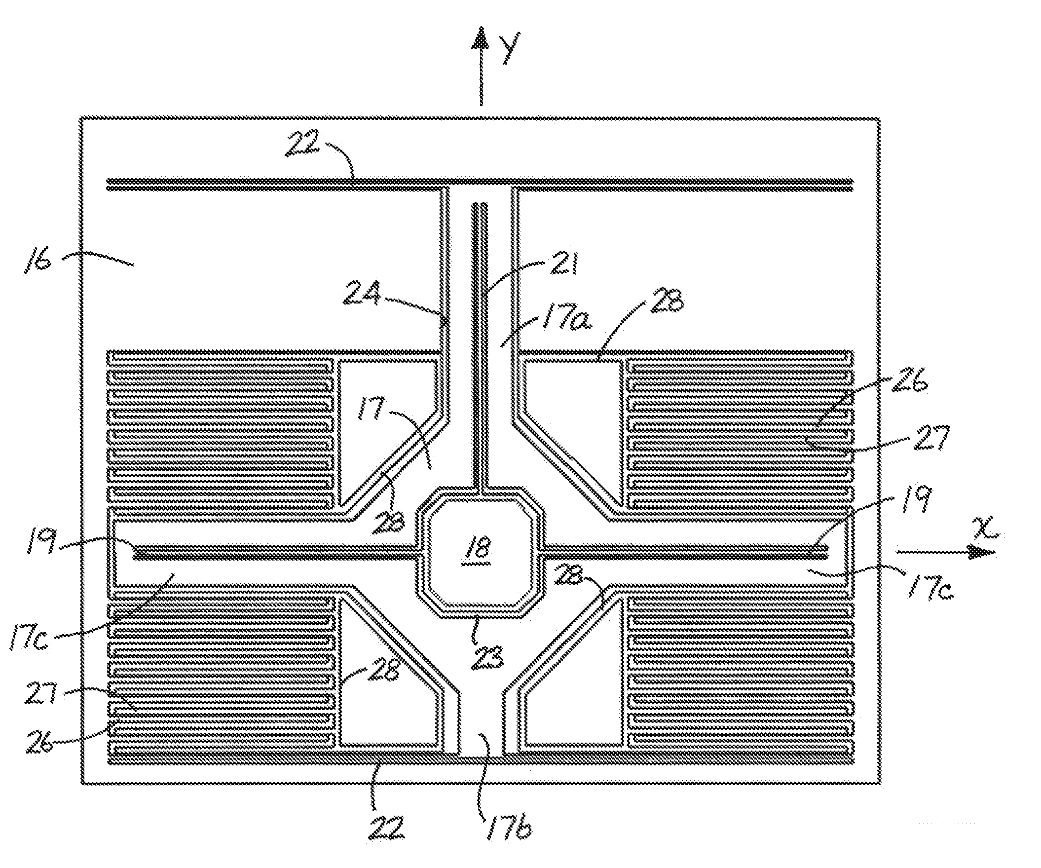
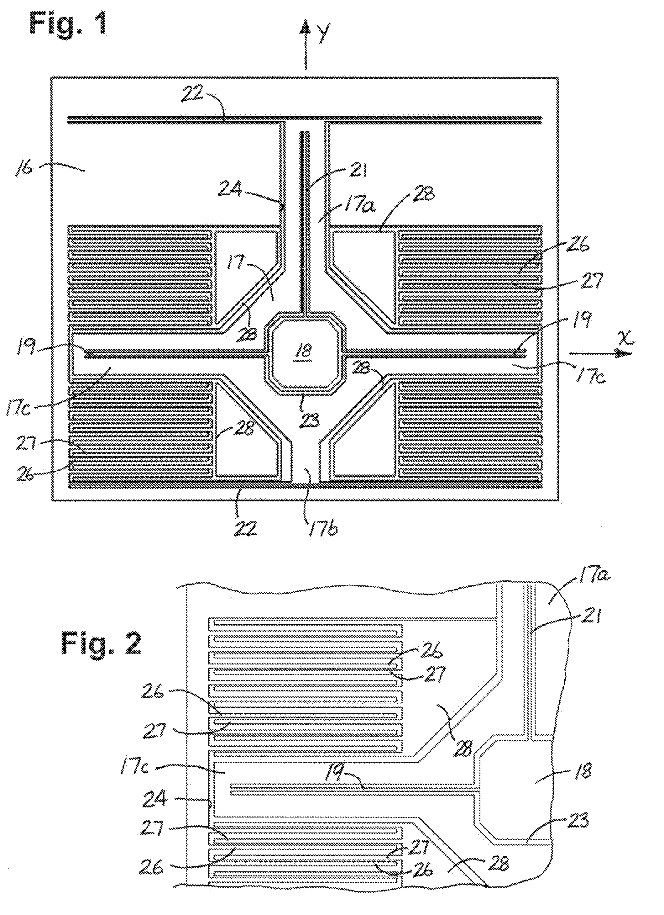
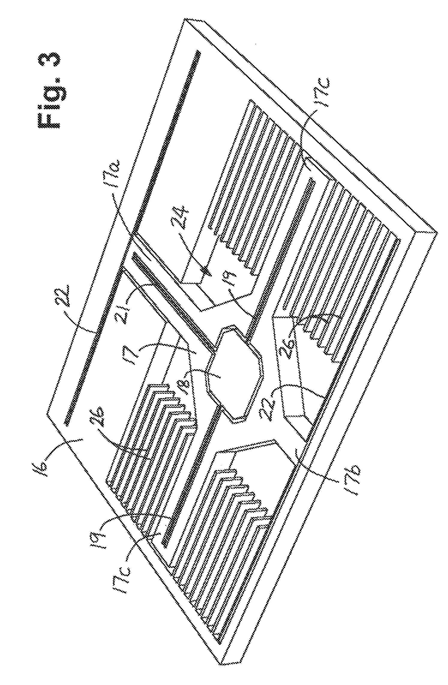
[0017]In the embodiment of FIGS. 1-6, the accelerometer has a single proof mass 16 suspended above a substrate for monitoring acceleration along mutually perpendicular x- and y-axes that lie in a plane parallel to the substrate.

[0018]The suspension for the proof mass includes a decoupling frame 17 which is suspended from a post 18 by flexible beams 19, 21 that extend along the x- and y-axes, respectively. The post is anchored to the substrate, and the beams prevent the decoupling frame from moving along the x- and y-axes while permitting it to rotate or move torsionally about a third axis (the z-axis) perpendicular to the x- and y-axes. The beams are relatively rigid in the z direction and prevent out-of-plane movement of the frame. Thus, the frame is constrained for torsional in-plane movement about the z-axis, with linear and torsional motion along and about other axes being suppressed.

[0019]The proof mass is suspended from the decoupling frame by flexible beams 22, 22 which exten...


PUM


Abstract

Micromachined accelerometer having one or more proof masses (16, 36, 37, 71, 72) mounted on one or more decoupling frames (17, 38, 39) or on a shuttle (73) such that the proof mass(es) can move along a first (y) axis in response to acceleration along the first axis while being constrained against movement along a second (x) axis and for torsional movement about a third (z) axis perpendicular to the first and second axes in response to acceleration along the second axis. Electrodes (26, 53, 54, 78, 79) that move with the proof mass(es) are interleaved with stationary electrodes (27, 56, 57, 81, 82) to form capacitors (A-D) that change in capacitance both in response to movement of the proof mass(es) along the first axis and in response to torsional movement of the proof mass(es) about the third axis, and circuitry (31-34) connected to the electrodes for providing output signals corresponding to acceleration along the first and second axes. The capacitances of two capacitors on each side of the second axis change in the same direction in response to acceleration along the first axis and in opposite directions in response to acceleration along the second axis. Signals from the capacitors that change capacitance in opposite directions both in response to acceleration along the first axis and in response to acceleration along the second axis are differentially combined to provide first and second difference signals, and the difference signals are additively and differentially combined to provide output signals corresponding to acceleration along the first and second axes.

Description

BACKGROUND OF THE INVENTION[0001]1. Field of Invention[0002]This invention pertains generally to inertial measurement systems and, more particularly, to a micromachined dual-axis accelerometer.[0003]2. Related Art[0004]One of the major challenges in the design of low-cost micromachined multi-axis accelerometers is minimizing the die size while maintaining high sensitivity. In most of the existing multi-axis accelerometers, separate proof masses with separate suspension beams and detection electrodes are utilized. Even though this allows the response due to acceleration along each axis to be isolated, duplicating the number of masses, electrodes and bonding areas is a major cost factor.SUMMARY OF THE INVENTION[0005]A micromachined dual-axis accelerometer has one or more proof masses and frames suspended above a substrate in a manner permitting movement of the proof mass(es) relative to the substrate along the first axis in response to acceleration along the first axis and also permit...

Claims


Application Information

Patent Timeline
Patent Type & Authority Applications(United States)
IPC IPC(8): G01P15/125
CPCG01P15/18G01P15/125G01P2015/0831
Inventor ACAR, CENKMAO, MINYAO
Owner CUSTOM SENSORS & TECH INC
Why Eureka
Try Eureka