Foam dispenser with liquid tube pump refill unit

a refill unit and foam dispenser technology, applied in the field of foam dispensers, can solve the problems of increasing the cost of a refill unit that includes the pump mechanism, and the cost of foam generating pumps is more expensiv

Inactive Publication Date: 2009-07-23
GOJO IND INC
View PDF5 Cites 55 Cited by
  • Summary
  • Abstract
  • Description
  • Claims
  • Application Information

AI Technical Summary

Benefits of technology

[0004]In light of the foregoing, this invention provides a dispenser including a housing and a refill unit. The housing includes an air bellows having and expanded volume and a compressed volume and retaining its expanded volume when the dispenser is not being actuated. The housing further includes a container support, a pump anvil, and a push bar. The push bar provides a pump plate portion and an air bellows actuator, and is capable of reciprocal movement toward and away from the pump anvil. The refill unit includes a container holding a foamable liquid, and a tube pump fluidly communicating with the foamable liquid in the container. The tube pump includes a collapsible tube, and the flow of foamable liquid into and out of the collapsible tube is regulated by a tube pump inlet valve and a tube pump outlet valve. The container fluidly communicates with the collapsible tube through the tube pump inlet valve. The refill unit further includes a mixing unit, and the collapsible tube communicates with the mixing unit through the tube pump outlet valve. The mixing unit includes an air bellows adaptor that is secured to an air outlet of the air bellows to fluidly communicate with the air bellows through an air bellows valve. The dispenser is actuated by moving the push bar toward the pump anvil, with such movement squeezing the collapsible tube between the push plate portion and the pump anvil to force foamable liquid therein through the tube pump outlet valve and into the mixing unit, such movement also causing the air bellows actuator to move the air bellows to its compressed volume to force air therein through the air bellows outlet valve and into the mixing unit.

Problems solved by technology

However, foam generating pumps are more expensive than liquid dispensing pumps, necessarily increasing the cost of a refill unit that includes the pump mechanism.

Method used


Image

  • Foam dispenser with liquid tube pump refill unit
  • Foam dispenser with liquid tube pump refill unit

Examples


Embodiment Construction

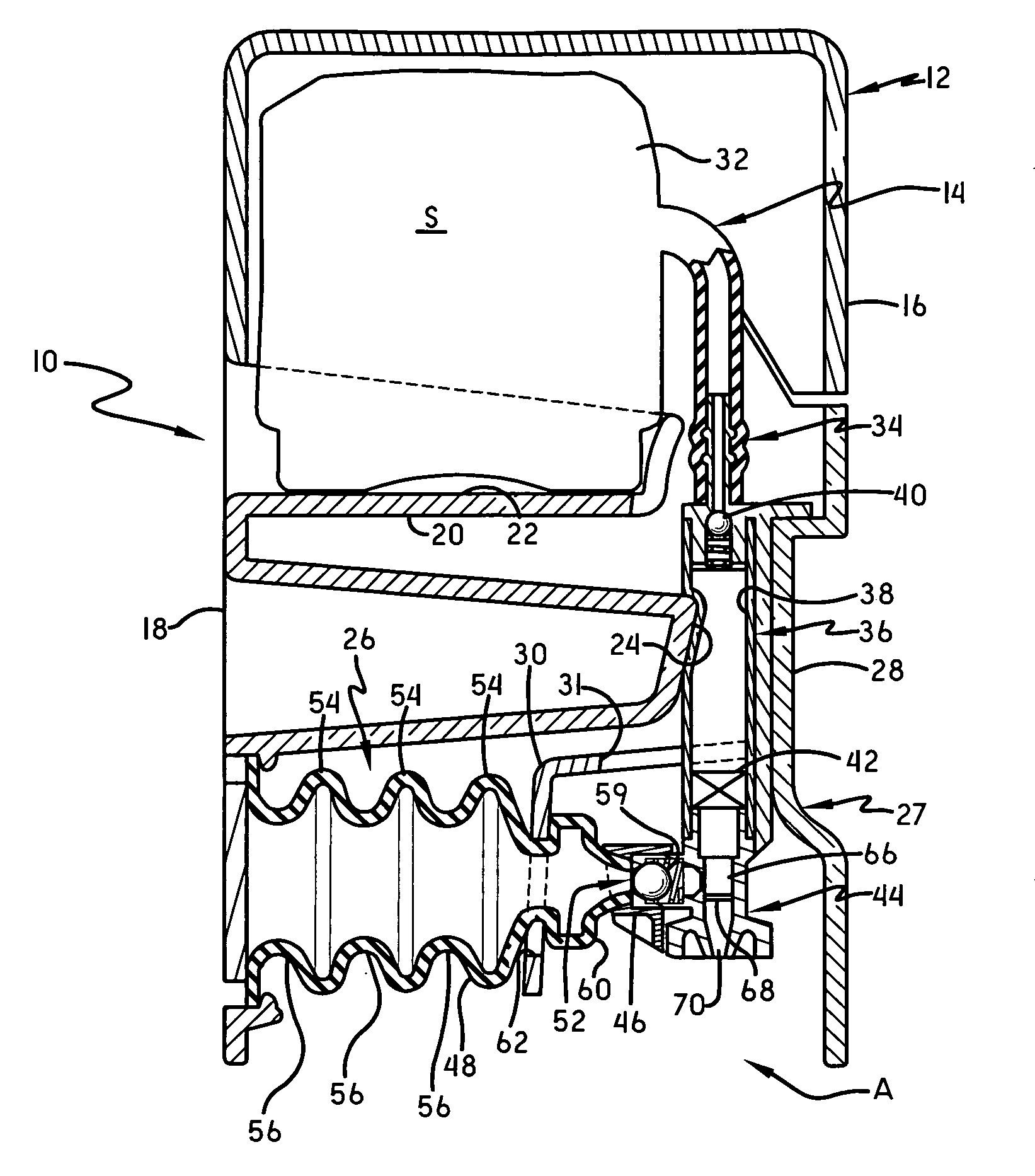
[0008]With reference to FIG. 1, the dispenser of this invention is shown and designated by the numeral 10. The dispenser 10 includes a housing 12 adapted to receive and hold a refill unit 14. Although the housing may take other forms, in this embodiment, the housing 12 is of the common type that includes a cover 16 secured to a backplate 18. A container support 20 is provided as part of backplate 18, here, in the form of a ledge 22. A pump anvil 24 is provided below the ledge 22, and an air bellows 26 extends outwardly from backplate 18 below the pump anvil 24. The cover 16 includes a push bar 27, which, when the cover 16 is closed on backplate 18, aligns over both the pump anvil 24 and the air bellows 26. More particularly, the push bar 27 provides a pump plate portion 28, which aligns with the pump anvil 24, and an air bellows actuator 30 that extends toward and connects to air bellows 26.

[0009]The refill unit 14 provides a container 32 holding a foamable liquid S. It is a collaps...


PUM

PropertyMeasurementUnit
volumeaaaaaaaaaa
compressed volumeaaaaaaaaaa
foamableaaaaaaaaaa

Abstract

A foam dispenser includes a housing and a refill unit. The refill unit carries a tube pump for pumping a foamable liquid, and the housing carries an air pump for pumping air. The tube pump and air pump fluidly communicate premixed chamber in a mixing unit to create a foam product when the dispenser is actuated to actuate both the 2 pump and the air pump.

Description

TECHNICAL FIELD[0001]The invention herein resides in the art of foam dispensers wherein a foamable liquid and air are combined to dispense a foam product. More particularly, the invention relates to a dispenser wherein a liquid tube pump is provided as part of a disposable refill unit containing the liquid, and an air pump is provided as part of the dispenser housing.BACKGROUND OF THE INVENTION[0002]For many years, it has been known to dispense liquids, such as soaps, sanitizers, cleansers, disinfectants, and the like from a dispenser housing maintaining a refill unit that holds the liquid and provides the pump mechanisms for dispensing the liquid. The pump mechanism employed with such dispensers has typically been a liquid pump, simply emitting a predetermined quantity of the liquid upon movement of an actuator. Recently, for purposes of effectiveness and economy, it has become desirable to dispense the liquids in the form of foam, generated by the interjection of air into the liqu...

Claims


Application Information

Patent Timeline
Patent Type & Authority Applications(United States)
IPC IPC(8): B67D5/58B67D5/52B65D37/00B67D7/76B67D7/70B67D7/74
CPCA47K5/14B01F3/04446B01F5/0683B01F5/0693G01F11/088B05B7/0037B05B11/303B05B11/3035B05B11/3087B01F15/0201B01F23/235B01F25/451B01F25/4523B01F35/71B05B11/103B05B11/1035B05B11/1087
Inventor CIAVARELLA, NICK E.HAYES, DAVID D.REYNOLDS, AARON R.
Owner GOJO IND INC
Why Eureka
Try Eureka