Rotating Electrical Machine

a technology of electrical machines and rotating parts, which is applied in the direction of magnetic circuit rotating parts, magnetic circuit shapes/forms/construction, electric devices, etc., can solve the problems of increasing temperature, increasing heat dissipation effect, and extremely low thermal conductivity of resin molded objects

Active Publication Date: 2009-07-23
HITACHI ASTEMO LTD
View PDF6 Cites 71 Cited by
  • Summary
  • Abstract
  • Description
  • Claims
  • Application Information

AI Technical Summary

Problems solved by technology

Rises in temperature are problematic because the rotating electrical machine is a compact, high-output rotating electrical machine.
The thermal conductivity of such resin molded articles is extremely low compared to metal components such as the stator coil and core.
This increases the heat dissipating effect.
Unfortunately, in patent document 1, the path taken by the coolant is such that the coolant only makes direct contact with surfaces of the coil ends.
This creates problems with regards to insulation.
However, this degrades cooling efficiency because the surface area of the coil the coolant flows when a motor is cooled directly by the coolant collides with is reduced by the brims.

Method used


Image

  • Rotating Electrical Machine
  • Rotating Electrical Machine
  • Rotating Electrical Machine

Examples


Embodiment Construction

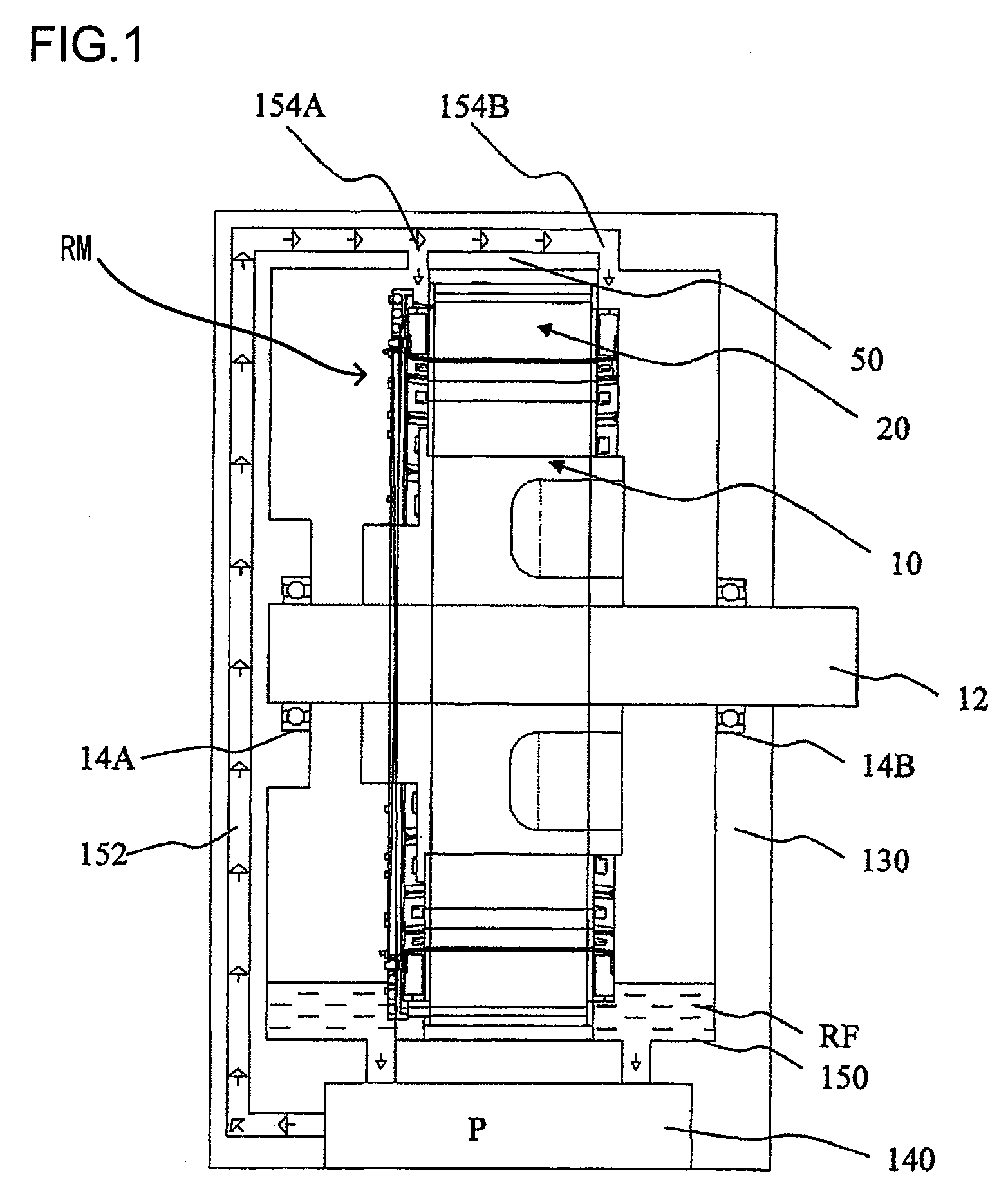
[0032]A description is now given of a configuration for a rotating electrical machine of an embodiment of the present invention using FIGS. 1 to 9.

[0033]First, a description is given of an overall configuration for a rotating electrical machine apparatus including the rotating electrical machine of this embodiment.

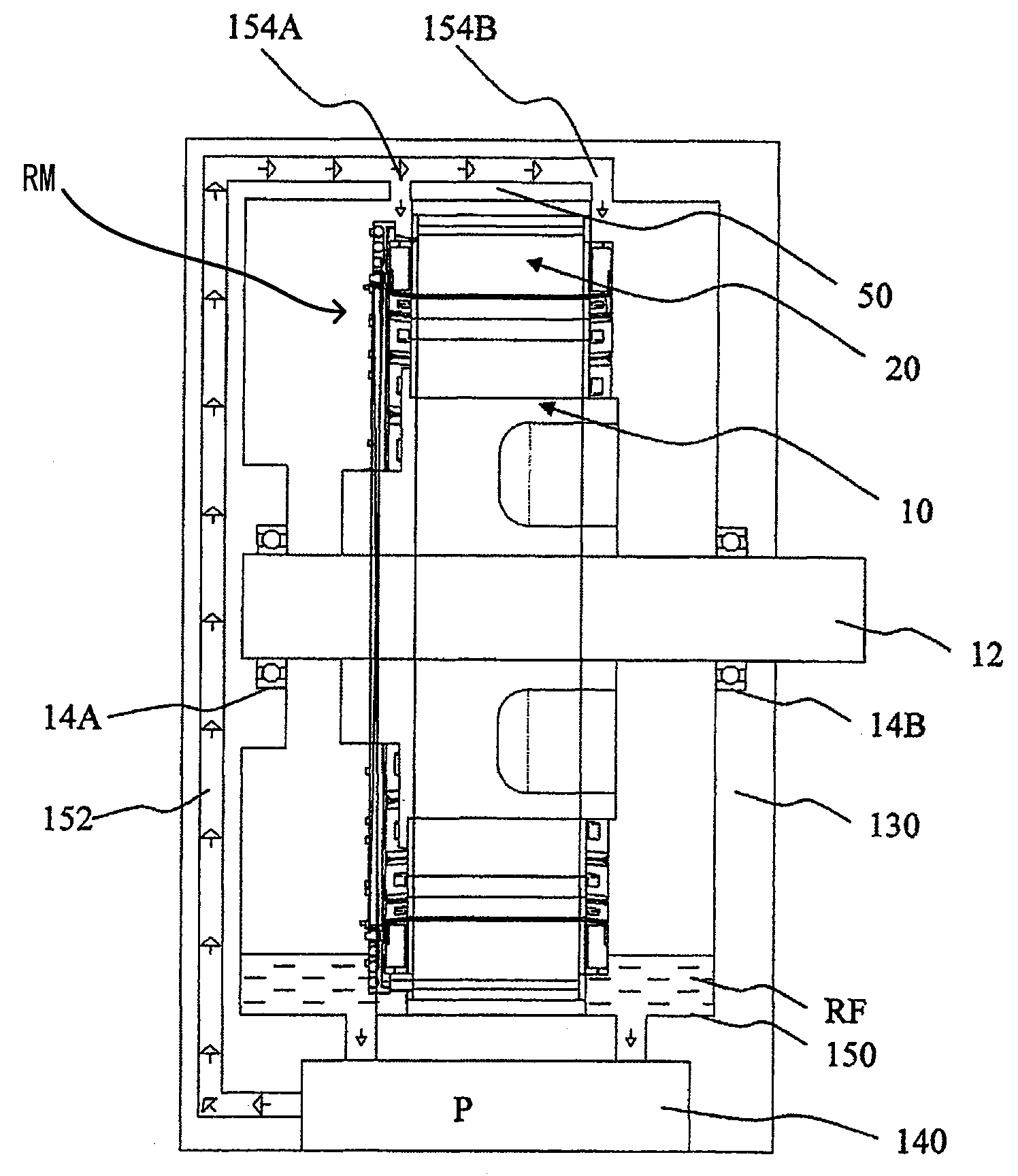
[0034]FIG. 1 is a cross-sectional view showing an overall configuration for the rotating electrical machine apparatus including the rotating electrical machine of the first embodiment of the present invention.

[0035]A rotating electrical machine RM used to describe this embodiment is for use with a hybrid vehicle. The rotating electrical machine RM is mounted between an engine ENG (refer to FIG. 10) and a transmission TM or is mounted within the transmission TM. It is necessary for the rotating electrical machine RM to be compact and have high output. This means that temperature rises are problematic and that it is necessary to rapidly dissipate heat generated by the stator...


PUM


Abstract

A rotating electrical machine includes: a stator that including a stator core and a teeth section, with a stator coil wound at the teeth section; a rotor arranged via a clearance at an inner periphery side of the stator and supported in a freely rotating manner; and a distribution unit supported by a resin holder, and including a conductor connected to the stator coil. The rotating electrical machine is cooled by coolant. The stator coil includes a coil end section projecting from an end of the stator in an axial direction. A gap is formed between an end of the stator core and a lower surface of the distribution unit by mounting the distribution unit on an upper part of the coil end section. The gap constitutes a path for the coolant.

Description

INCORPORATION BY REFERENCE[0001]The disclosure of the following priority application is herein incorporated by reference:[0002]Japanese Patent Application No. 2007-323637 filed Dec. 14, 2007.BACKGROUND OF THE INVENTION[0003]1. Field of the Invention[0004]The present invention relates to a rotating electrical machine, and particularly relates to a liquid-cooled rotating electrical machine.[0005]2. Description of Related Art[0006]At a front wheel, rear wheel, or four-wheel drive vehicle that is mainly powered by a rotating electrical machine only or an engine and a rotating electrical machine, the rotating electrical machine is fitted between the engine and a transmission or is fitted within the transmission and the rotating electrical machine is mechanically connected to the engine and the transmission. Rises in temperature are problematic because the rotating electrical machine is a compact, high-output rotating electrical machine. It is therefore necessary to rapidly dissipate heat...

Claims


Application Information

Patent Timeline
Patent Type & Authority Applications(United States)
IPC IPC(8): H02K9/19
CPCH02K3/24Y02T10/641H02K9/19B60L1/003B60L1/02B60L3/0061B60L7/14B60L11/14B60L2210/40B60L2220/14B60L2240/36B60L2240/423B60L2240/425B60L2240/429B60L2260/28B60L2220/50Y02T10/7077Y02T10/7241Y02T10/642Y02T10/70H02K3/522B60L50/16Y02T10/64Y02T10/72Y02T10/7072
Inventor HOSHINO, KATSUHIRONAKAYAMA, KENICHIKAJIYA, NOBUYUKIKOIZUMI, TAKAYUKIUEDA, TOSHIAKI
Owner HITACHI ASTEMO LTD
Why Eureka
Try Eureka