Conductor bar for a rotating electrical machine

Inactive Publication Date: 2009-07-23
GENERAL ELECTRIC TECH GMBH
View PDF28 Cites 2 Cited by
  • Summary
  • Abstract
  • Description
  • Claims
  • Application Information

AI Technical Summary

Benefits of technology

[0013]An aspect of the invention is to provide a conductor bar in which the breakdown probability at the edge is reduced.

Problems solved by technology

However, it is virtually impossible to achieve more than ri=2.5 mm since greater rounding cannot be achieved without grinding onto the conductor elements 12 (and thus constricting the current path).

Method used


Image

  • Conductor bar for a rotating electrical machine
  • Conductor bar for a rotating electrical machine
  • Conductor bar for a rotating electrical machine

Examples


Embodiment Construction

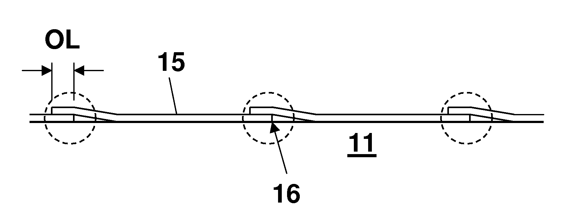
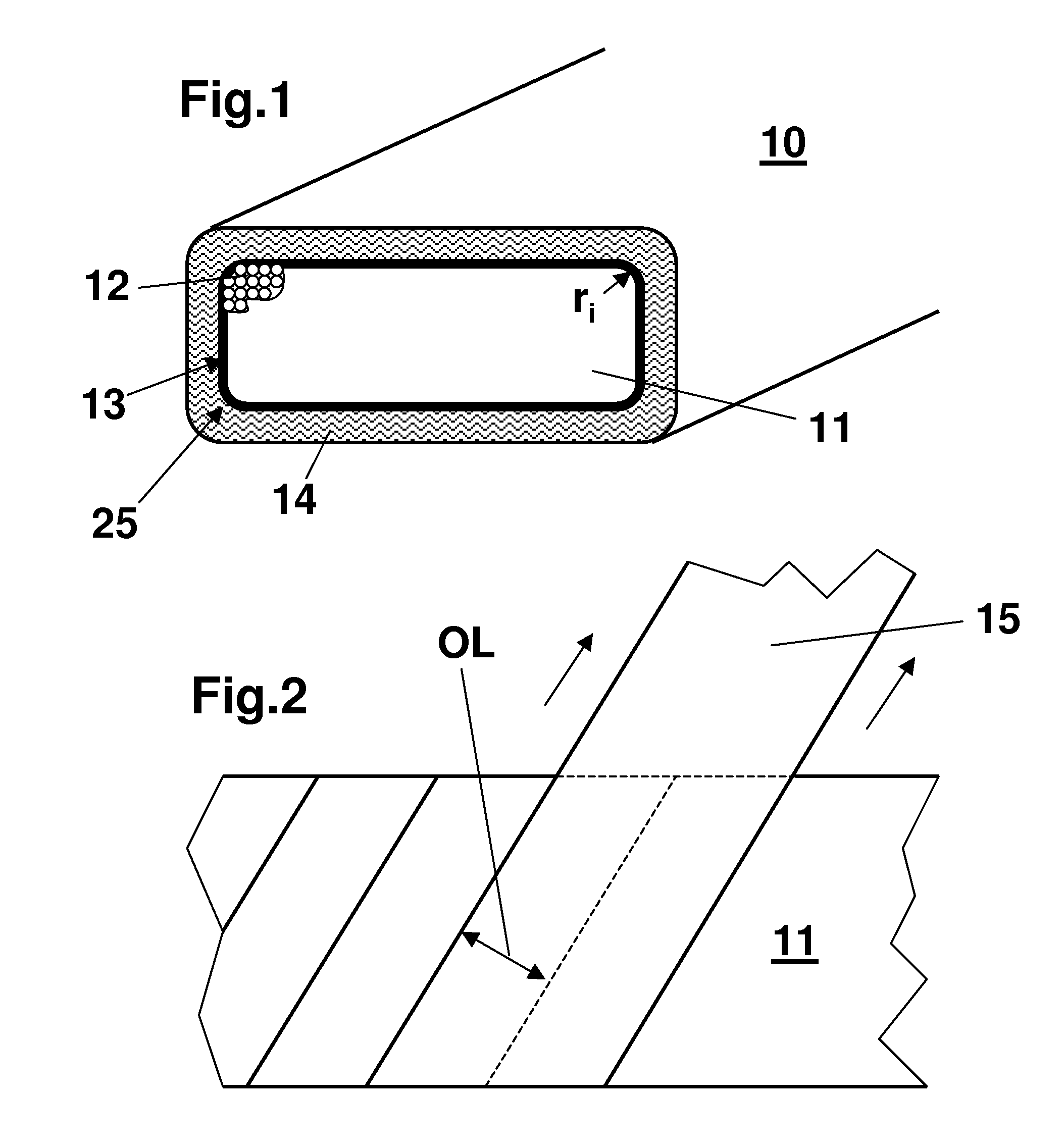
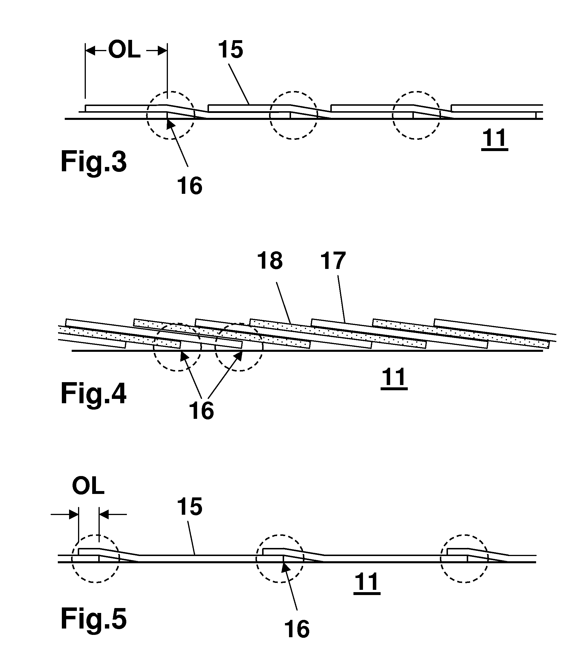
[0033]In the first exemplary embodiment of the invention, a decrease is achieved in the breakdown probability on the longitudinal edge 25 of the inner conductor 11 by winding a mica tape of normal width in only one layer, with an overlap OL which is reduced in comparison to the conventional winding technique (FIG. 5). This considerably reduces the frequency of the edges 16 per unit length of the conductor bar in the longitudinal direction.

[0034]In the overlap limiting case of 0 (FIG. 6), that is to say with the winding forming a butt joint 19, the frequency of the edge is reduced by a factor of 4 in comparison to the prior art. In this preferred embodiment of the butt-jointed winding, the butt joint 19 in the first mica tape 17 is covered by a second, likewise butt-jointed, layer of a mica tape 18. This type of winding should be restricted to the straight part of the conductor bar 10 (which is located in the winding slot) since it is not possible to wind with a butt joint in the cur...


PUM


Abstract

A conductor bar for a rotating electrical machine has an inner conductor with an essentially rectangular cross section sheathed in a straight section of the conductor bar by mica tape insulation.

Description

[0001]Priority is claimed to German Patent No. DE 10 2008 000 073.6, filed on Jan. 17, 2008, the entire disclosure of which is incorporated by reference herein.[0002]The present invention relates generally to the field of rotating electrical machines, and in particular to a conductor bar for a rotating electrical machine.BACKGROUND [0003]In large rotating electrical machines, windings which are composed of individual conductor bars are used in the area of the stator and / or rotor. The conductor bars, which normally have a rectangular cross section, are inserted with a straight part into corresponding axial slots in the stator body or rotor body, and are connected to one another in an end winding at the ends which project out of the body (EP-A2-1 653 588). By way of example, the conductor bars are designed as illustrated in FIG. 1: the conductor bar 10 has an electrically conductive inner conductor 11 composed of copper, which generally comprises a multiplicity of conductor elements 1...

Claims


Application Information

Patent Timeline
IPC IPC(8): H02K3/40H02K3/34
CPCH02K3/40
Inventor BAUMANN, THOMAS
Owner GENERAL ELECTRIC TECH GMBH
Why Eureka
Try Eureka