
Liquid crystal display and dimming controlling method thereof

Active Publication Date: 2009-07-23
LG DISPLAY CO LTD
View PDF5 Cites 41 Cited by
  • Summary
  • Abstract
  • Description
  • Claims
  • Application Information

AI Technical Summary

Benefits of technology

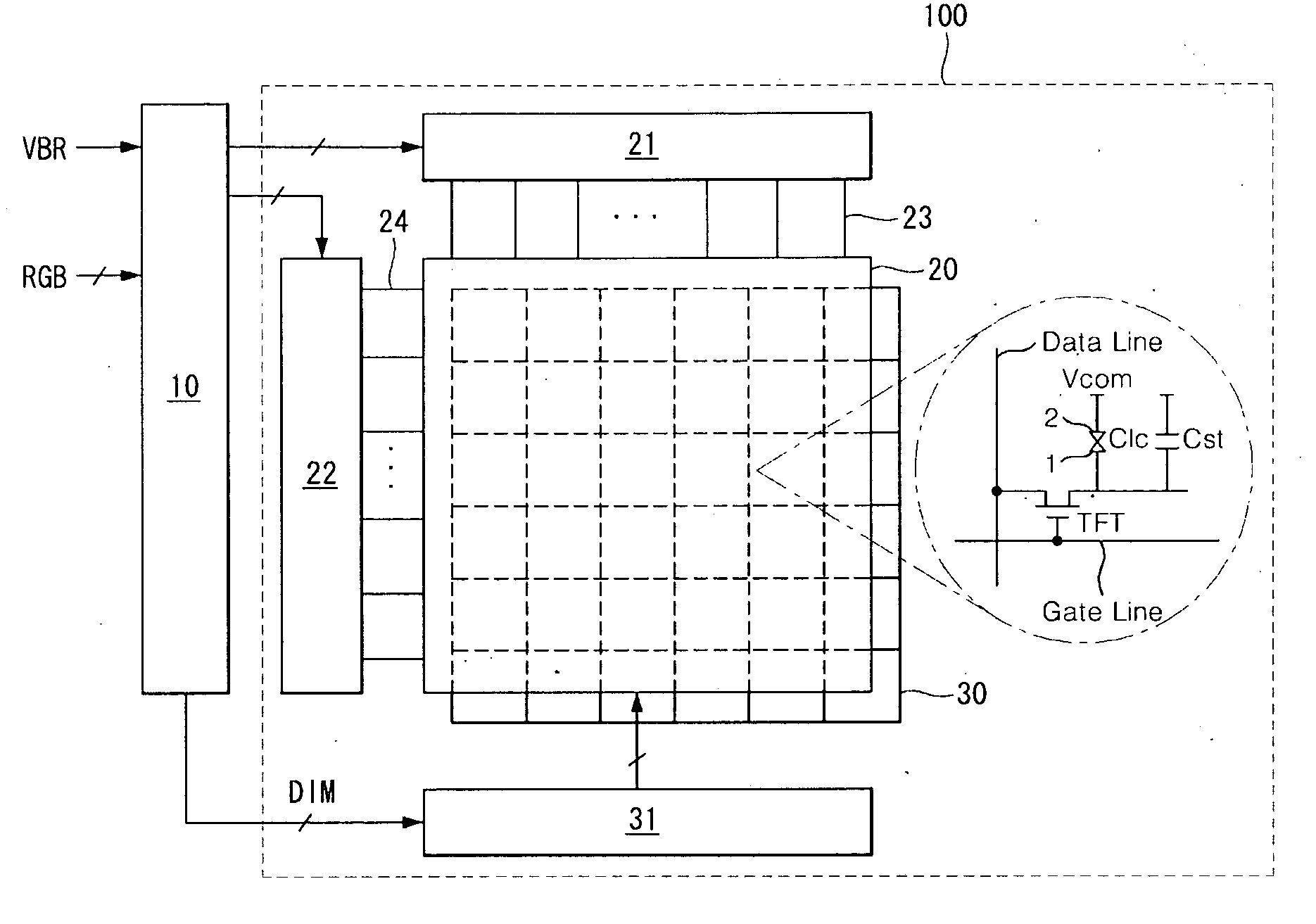
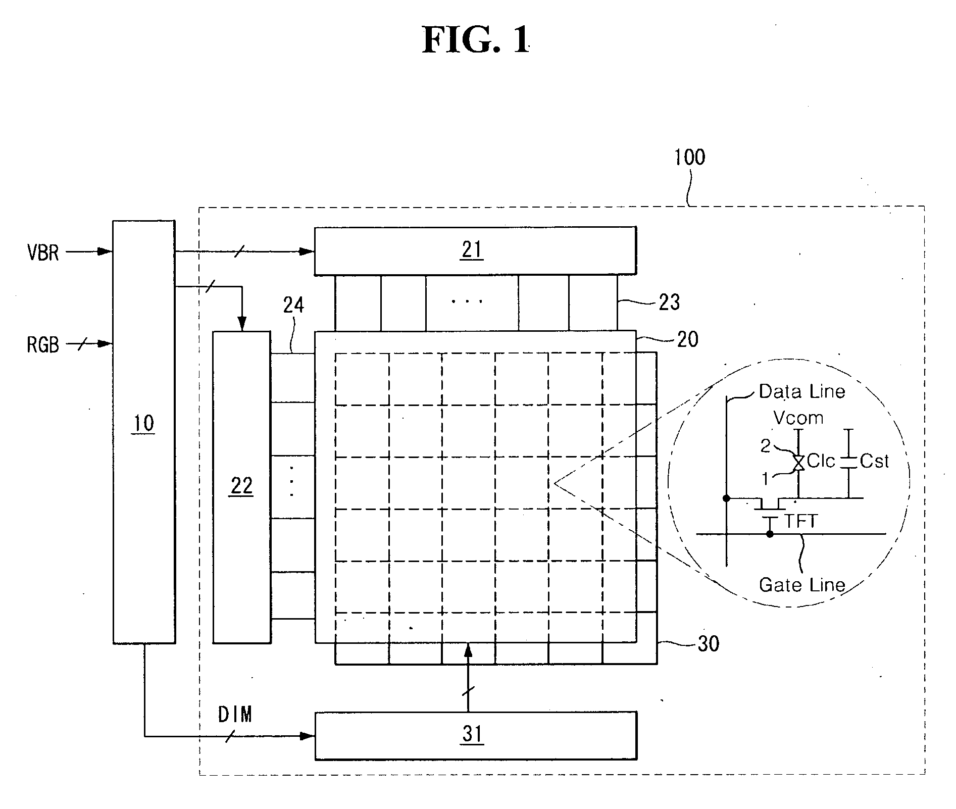
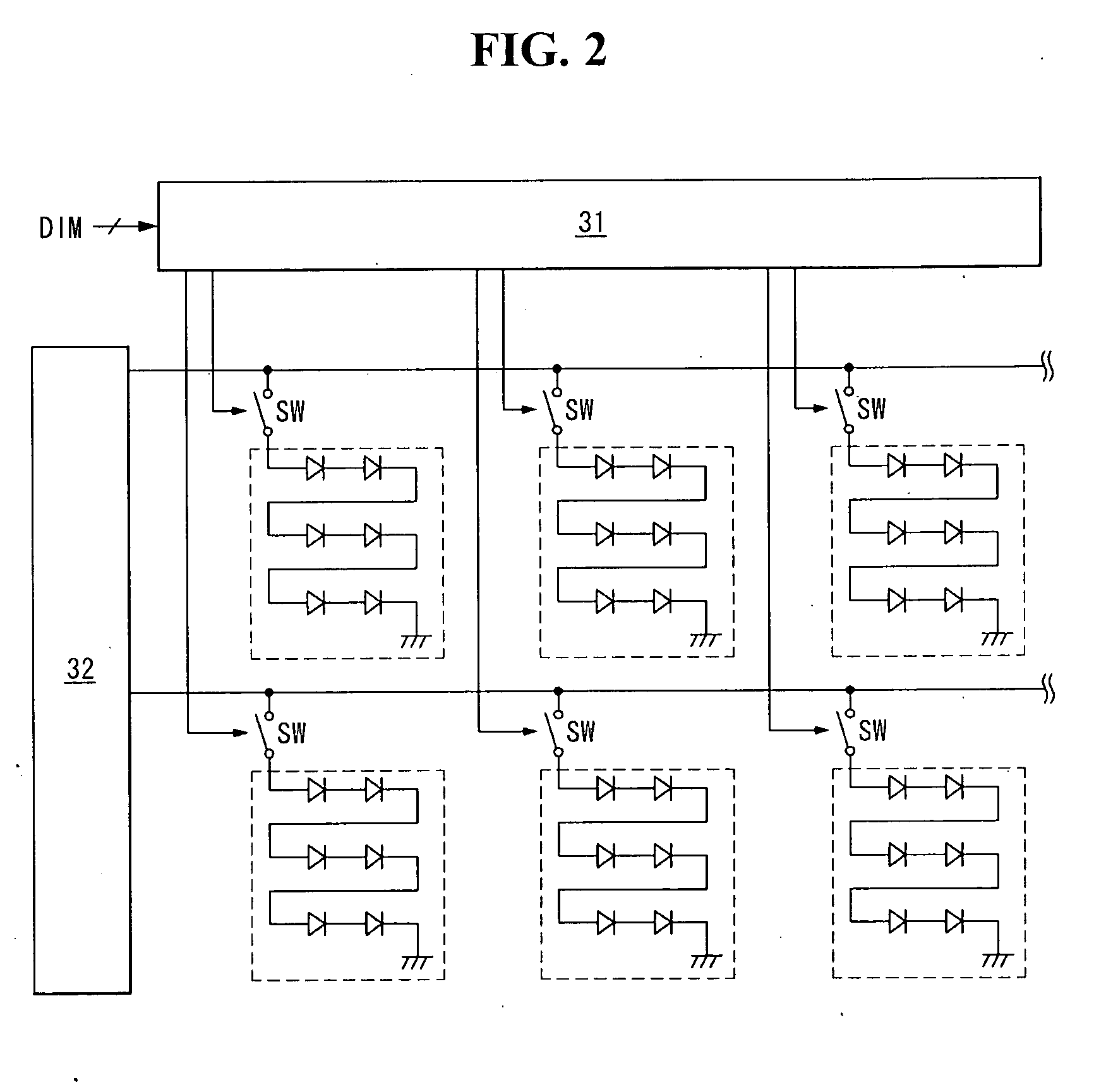
[0007]Therefore, to solve the above mentioned drawbacks and problems, the purpose of the exemplary embodiments suggest the liquid crystal display device for enhancing the contrast characteristics and reducing the electric consumption power by simplifying the dimming circuit for realizing local dimming, and the dimming control method thereof.

Problems solved by technology

However, the conventional local dimming method causes the luminescence unevenness and flickers between neighboring blocks divided in the display panel.
Further, for realizing the local dimming circuit, a lot of circuit elements are required so that the circuit configuration is complex and the algorithm for driving the circuit is very complicated.

Method used


Image

  • Liquid crystal display and dimming controlling method thereof
  • Liquid crystal display and dimming controlling method thereof
  • Liquid crystal display and dimming controlling method thereof

Examples


first embodiment

[0035] the method for extracting the representative value of each blocks, in each pixel of selected blocks as shown in FIG. 4, the maximum value is calculated among the digital video data (RGB) of Red (R), Green (G) and Blue (Blue). The maximum value (P(n)) of each pixel can be represented as following Equation (1).

P(n)=Max(R(n),G(n),B(n))  (1)

[0036]Further, the method for extracting the representative value of each block according to the first embodiment includes the calculation of the total summation of maximum values of each pixel in relative block. The calculation result of this total summation, as the representative value of the block, is represented by the following Equation (2).

Representativevalueoftheblock=∑i-0n∑j=0mP(i,j)(2)

second embodiment

[0037] the method for extracting the representative value of each block includes the calculating, in the selected block, the total summation of R data (Rtotal) as shown in Equation (3), the total summation of G data (Gtotal) as shown in Equation (4), and the total summation of B data (Btotal) as shown in Equation (5), separately.

Rtotal=∑i=0n∑j=0mR(i,j)(3)Gtotal=∑i=0n∑j=0mG(i,j)(4)Btotal=∑i=0n∑j=0mB(i,j)(5)

[0038]The method for extracting the representative value of each block according to the second embodiment may include calculating the luminescence (Y) with the total value of the R, G and B data acquired by Equation (6) separately, as a function.

Y=0.229*Rtotal+0.587*Gtotal+0.114*Btotal  (6)

[0039]The set maker or user can select any one algorithm of the two methods for extracting the representative value of each block as the algorithm of the block video analysis 11.

[0040]The block dimming decisioner 12 converts the representative values of each block calculated by the block video an...


PUM


Abstract

A liquid crystal display device and a dimming controlling method thereof are disclosed. The liquid crystal display device includes a liquid crystal display panel, a drive circuit supplying a data pulse and a gate pulse to the liquid crystal display panel, a backlight unit divided into a plurality of block including light sources, and irradiating lights of which luminescence is controlled by the blocks, respectively, a controller analyzing an input video data by the block unit, generating a block dimming value based on a result of the analyzing, repeating a low pass filtering to the block dimming value to generate a local dimming value, applying a predeterminded global dimming value to an average of the local dimming value to generate a dimming signal, and a backlight driver generating a PWM signal for controlling a luminescence of the light sources by the blocks respectively according to the dimming signal to drive the light sources by the blocks respectively.

Description

[0001]This application claims the benefit of Korea Patent Application No. 10-2008-0007282 filed on Jan. 23, 2008, which is incorporated herein by reference for all purposes as if fully set forth herein.BACKGROUND OF THE INVENTION[0002]1. Field of the Invention[0003]Exemplary embodiments relate to a liquid crystal display device and a dimming controlling method thereof.[0004]2. Discussion of the Related Art[0005]The active matrix liquid crystal display device represents moving pictures using the thin film transistor (or “TFT”) as the switching elements. Comparing to the cathode ray tube (or “CRT”), the liquid crystal display device can be made in small size and light weight so that it can actively applied to the portable information devices, office automation devices, and computers. Further, it can be effectively applied to the television set replacing with the CRT.[0006]As the liquid crystal display device is not self-luminescent element, the liquid crystal display device requires a...

Claims


Application Information

Patent Timeline
IPC IPC(8): G09G3/36
CPCG09G2360/16G09G3/3426G09G2330/021G09G2320/066G09G2320/064G09G3/36G02F1/133G02F1/1335H05B41/38
Inventor PARK, JOONKYUKIM, JONGHOONCHOI, RAKWOO
Owner LG DISPLAY CO LTD
Learn More