Fiber optic probe and related apparatus, systems and methods for making optics-based measurements of liquid samples

a fiber optic probe and liquid sample technology, applied in the field of fiber optic probes, can solve the problems of inability to remove such non-analytical components of the media being irradiated, still a significant source of analytical errors and noise in conventional systems, and produce inaccurate data

Active Publication Date: 2009-07-23
AGILENT TECH INC
View PDF10 Cites 14 Cited by
  • Summary
  • Abstract
  • Description
  • Claims
  • Application Information

AI Technical Summary

Problems solved by technology

Nonetheless, non-analytical components of the media being irradiated, such as bubbles and particulates, are still a significant source of analytical errors and noise in conventional systems, as described below.
Unfortunately, probes 104 designed as illustrated in FIG. 1 are not capable of removing such non-analytical components 164 from the sample target region 124.
The non-analytical components 164 tend to interfere with the UV scan and consequently produce inaccurate data.
However, because each sample dosage form has unique particulate features, every sample being tested requires a separate algorithm for correcting the errors caused by the particulates of the dosage form.
Nonetheless, the fact that the probe is constantly submerged means that hydrodynamic influences can still affect the release rate of the dosage formulation being tested.
Moreover, regardless of whether the probe is integrated with a stirring shaft or provided separately, no provision is made for eliminating interference by bubbles and particulates within the sample target region of the probe and thus analytical errors are still a problem.
This patent emphasizes the need to avoid the use of mirrors, but introduces other problems.
The optical alignment achieved by this design is less than optimal.
Even the slightest movement of the opposing pair of fiber ends may cause a significant loss of light transmission.
The resulting adverse effect on performance may worsen over time and may vary from one instance of operation to another.
The resulting design introduces a number of geometric / structural features in the test vessel that may increase the amount of turbulence or flow aberration in the dissolution media and thus increase analytical errors.

Method used


Image

  • Fiber optic probe and related apparatus, systems and methods for making optics-based measurements of liquid samples
  • Fiber optic probe and related apparatus, systems and methods for making optics-based measurements of liquid samples
  • Fiber optic probe and related apparatus, systems and methods for making optics-based measurements of liquid samples

Examples


Embodiment Construction

[0028]In general, terms such as “communicate” and “in . . . communication with” (for example, a first component “communicates with” or “is in communication with” a second component) are used herein to indicate a structural, functional, mechanical, electrical, signal, optical, magnetic, electromagnetic, ionic or fluidic relationship between two or more components or elements. As such, the fact that one component is said to communicate with a second component is not intended to exclude the possibility that additional components may be present between, and / or operatively associated or engaged with, the first and second components.

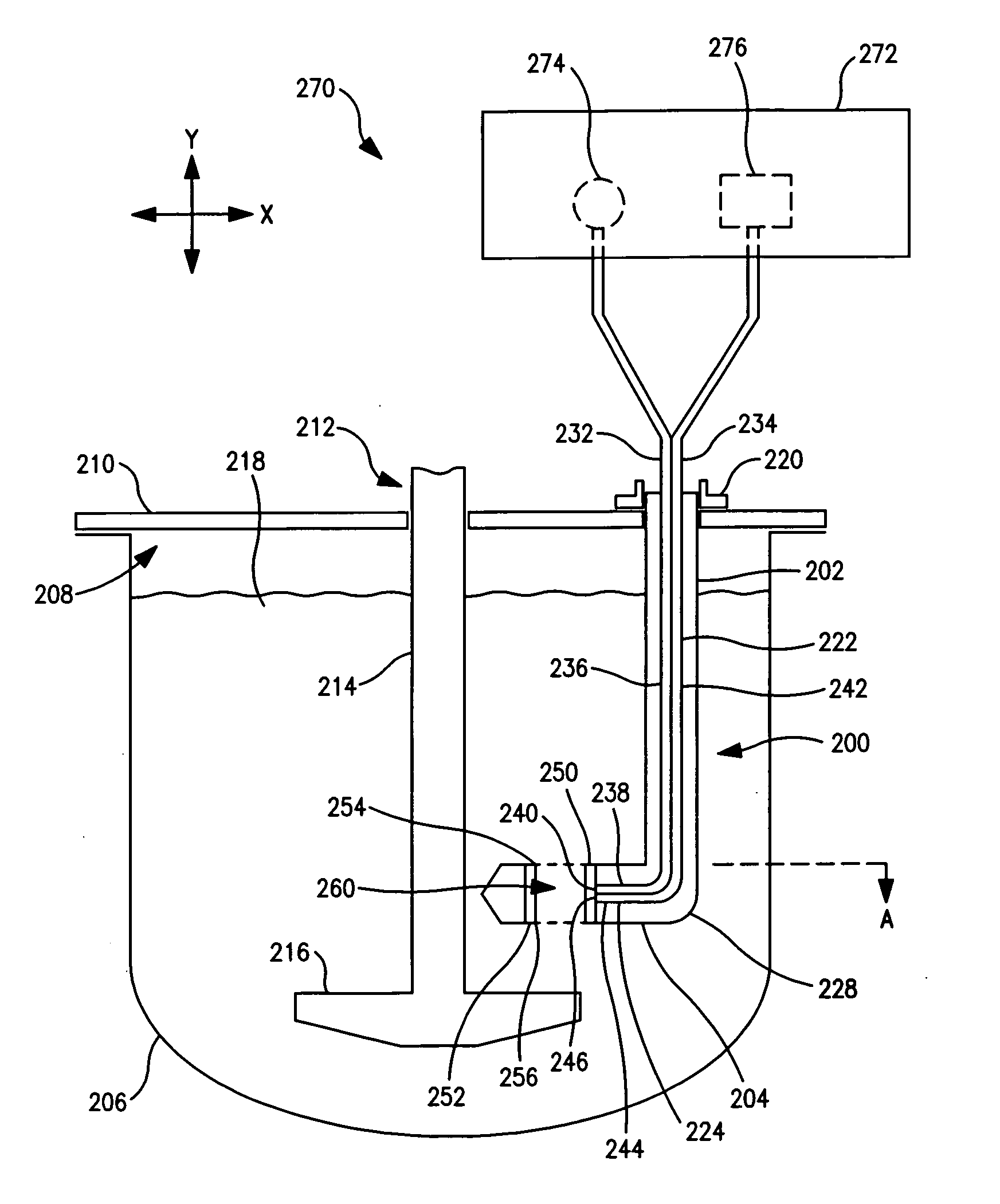
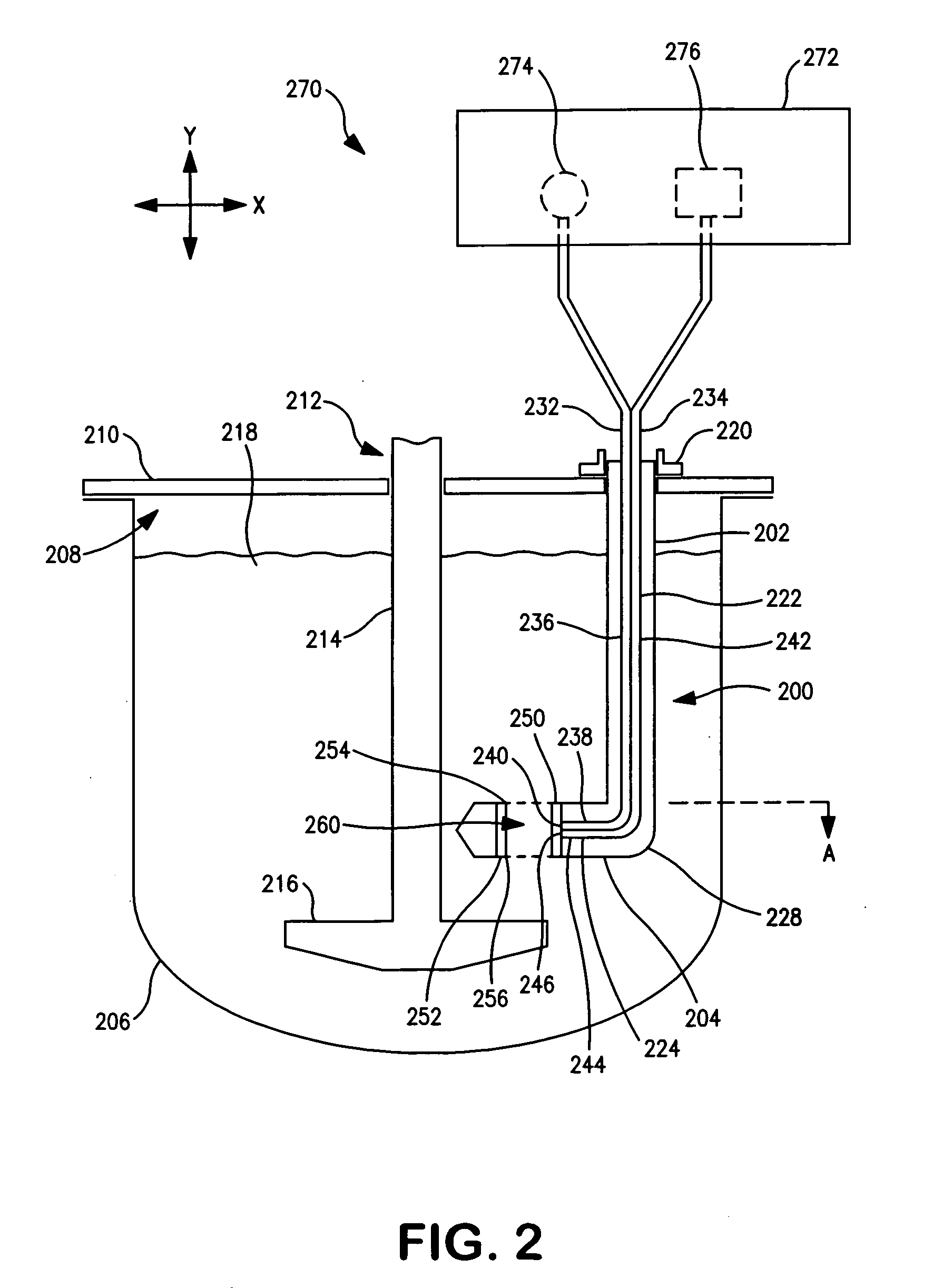
[0029]The subject matter disclosed herein generally relates to the analysis of liquid media by optical means. Examples of implementations of methods and related devices, apparatus, and / or systems are described in more detail below with reference to FIGS. 2-6. Some of these examples are described in the context of dissolution testing. However, any process that ...


PUM


Abstract

A fiber-optic probe includes first and second optical fibers disposed in a body, a liquid sampling region between ends of the fibers and a reflector, and apertures communicating with the sampling region. The probe may be inserted in media in a vessel. Optical signals are transmitted through the first fiber, the sampling region and second fiber. The sampling region is offset from other parts of the probe so that bubbles or particulates flow out from the sampling region without being obstructed by the probe.

Description

FIELD OF THE INVENTION[0001]The present invention relates generally to making an optics-based measurement of a liquid sample by utilizing fiber optics to route optical signals to and from the liquid sample. Such optical signals may be utilized to measure a property of the liquid sample such as, for example, the concentration of an analyte of interest. More particularly, the present invention relates to a fiber-optic probe useful for making such measurements.BACKGROUND OF THE INVENTION[0002]Optical transport techniques may be utilized to direct a beam or pulse of light from a light source (e.g., lamp, light-emitting diode or LED, laser, laser diode or LD, etc.) to a test site to irradiate sample material and, subsequently, conduct a resulting optical beam or pulse generated at the test site to a suitable light receiving device (e.g., an optical detector or sensor such as a photocell). Irradiation of the sample results in analytical information being encoded in the optical signal that...

Claims


Application Information

Patent Timeline
Patent Type & Authority Applications(United States)
IPC IPC(8): G02B27/02
CPCG01N2021/8514G01N21/8507
Inventor CRIST, GEORGE BRYANFERNANDO, C.J. ANTHONY
Owner AGILENT TECH INC
Why Eureka
Try Eureka