Air distributing apparatus for reducing energy consumption

a technology of air distribution apparatus and energy consumption, which is applied in the direction of lighting and heating apparatus, ventilation systems, heating types, etc., can solve the problems of waste of energy, many parts of the apparatus, and less efficient system, so as to achieve the effect of reducing energy consumption

Inactive Publication Date: 2009-07-23
FARRELL GERALD
View PDF22 Cites 35 Cited by
  • Summary
  • Abstract
  • Description
  • Claims
  • Application Information

AI Technical Summary

Benefits of technology

[0007]Accordingly, there is provided an air distributing assembly. More specifically, there is provided an air distributing assembly that combines an occupancy sensor and a damper for specifically directing air flow within a space so as to control space temperature and minimize energy consumption.

Problems solved by technology

However, typically the buildings' air conditioning systems do not register which spaces are unoccupied and continue to supply heated or chilled air to cater for the perimeter external heat gains or losses so as to maintain space temperatures.
However, because Wilson merely suggests the addition of cool or hot air into a space, it suffers of a number of disadvantages.
Wilson requires many parts and does not provide a means for a tailored distribution of air in a space.
This lack of targeting results in wasted energy and therefore a less efficient system.
Also, Wilson does not provide a means of re-using existing energy within a building and this further hinders the energy efficiency of such a device.
Mention is made of the possibility of using an occupancy sensor; however Kates lacks a teaching of strategically tailored distribution of air in a given room.

Method used


Image

  • Air distributing apparatus for reducing energy consumption
  • Air distributing apparatus for reducing energy consumption
  • Air distributing apparatus for reducing energy consumption

Examples


Embodiment Construction

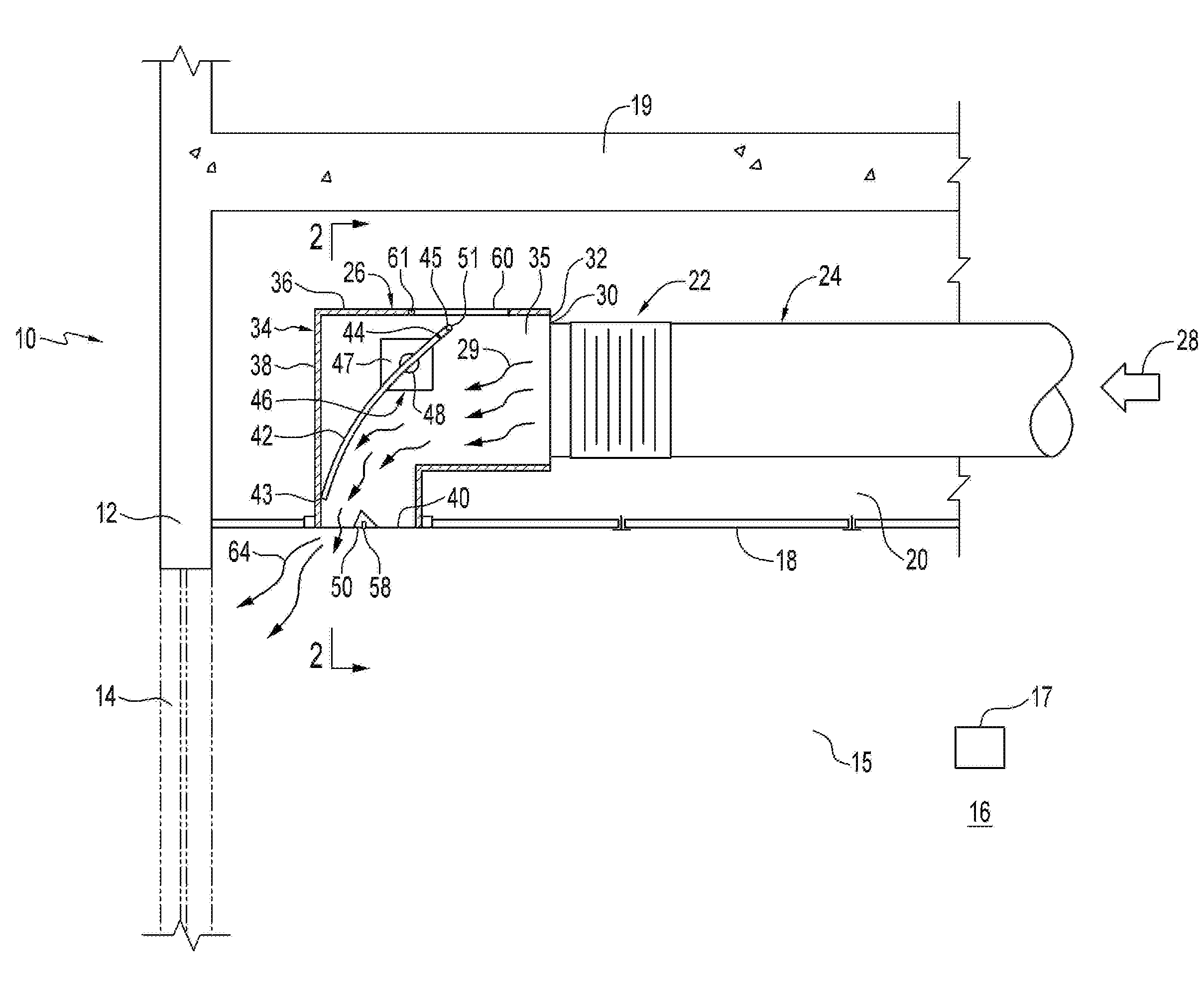
[0026]Referring to FIG. 1, there is illustrated a building structure 10. The building structure 10 has an exterior wall 12, a window 14 and a back wall 16 on which may be attached a temperate sensor 17 having a target temperature setting. The building structure 10 defines a space 15, which may be enclosed. The building structure 10 includes a ceiling 18 and a plenum 20 positioned perpendicular to the window 13. The plenum 20 extends between ceiling 18 and floor 19 above.

[0027]An air distributing assembly 22 is located within the plenum 20. The air distributing assembly 22 includes a supply duct 24 and an air distributing apparatus 26. The supply duct 24 is in communication with a primary air supply as indicated by arrow 28. The primary air supply 28 contributes to a stream of air 29 which in this example comprises heated air and which passes through the air distributing apparatus 26. The supply duct 24 has a terminal 30.

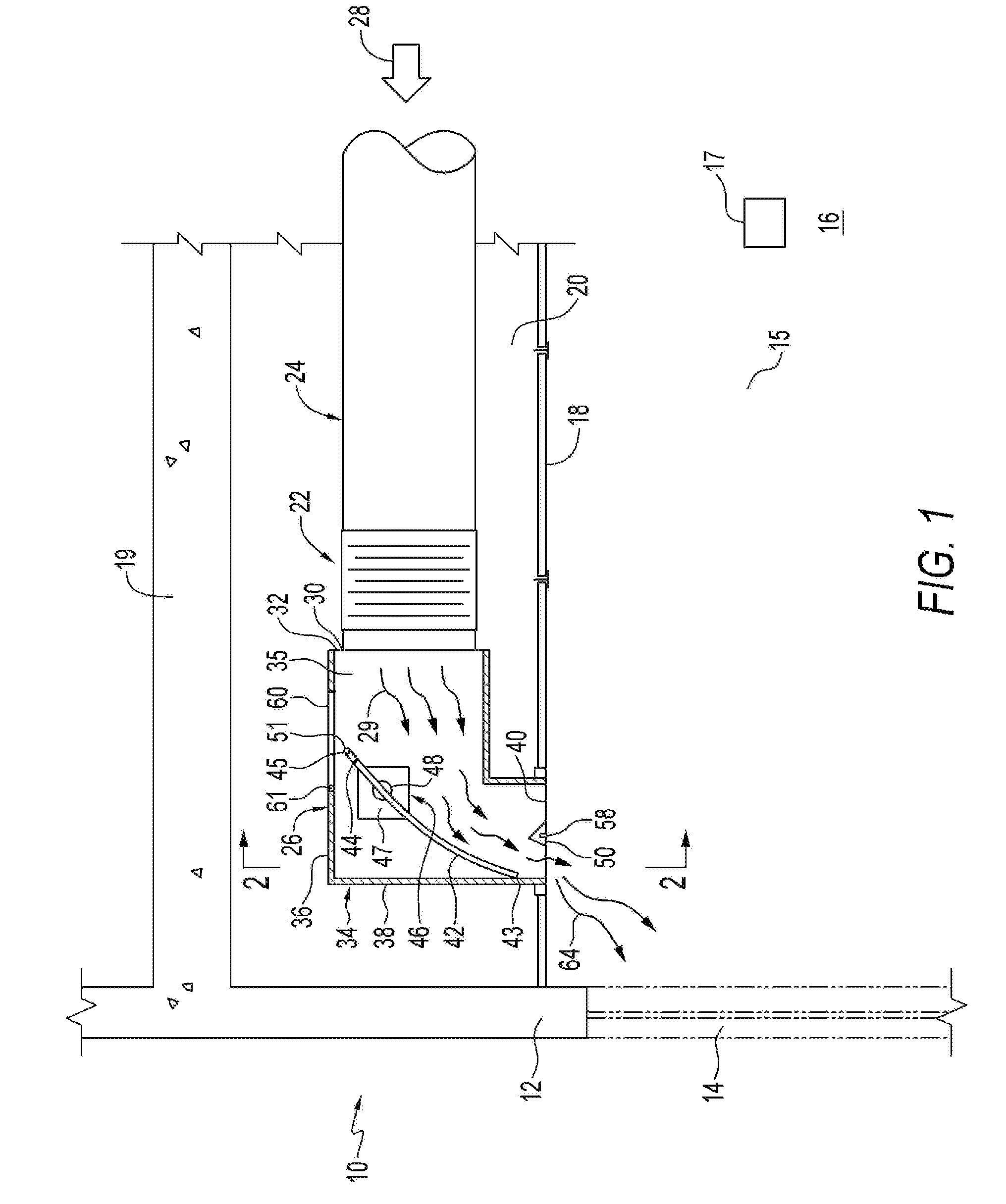
[0028]The air distributing apparatus 26 includes a diffuser 34 ...


PUM


Abstract

The invention involves an air distributing apparatus for installation in a diffuser. The apparatus includes a first damper positioned within the diffuser. The first damper also has an open mode where a stream of air can exit the diffuser to a space. The first damper has a closed mode where the damper inhibits the stream of air from exiting the diffuser. The apparatus includes an actuator operatively connected to the first damper. There is an occupancy sensor positioned and configured to distinguish whether the space is occupied or unoccupied by a person. The occupancy sensor is in communication with the actuator. When the space is occupied by the person, the occupancy sensor communicates with the actuator to thereby cause the first damper to be positioned in the open mode. When the space is unoccupied, the occupancy sensor communicates with the actuator to thereby cause the first damper to be positioned in the closed mode. A remote temperature sensor varies the volume of supply air entering the space depending on the prevailing air conditioning load.

Description

BACKGROUND OF THE INVENTION[0001]In keeping with today's demand for energy saving and sustainable buildings, more energy efficient designs are a necessity. The heating, ventilating, and air-conditioning (“HVAC”) systems in large buildings are the main consumers of electricity, gas and water. These systems therefore need to be designed to incorporate equipment which will minimize not only the utilities consumed in their operation, but also the overall consumption of natural resources and environmental impacts associated with their manufacture and transportation. It is generally agreed that most office staff prefer to have a perimeter office with a window, and it is these perimeter spaces that have by far the greatest demand, based on an energy per square foot basis, on the building's HVAC system. Interior spaces usually have less occupancy density and are used for storage, filing, equipment rooms etc.[0002]Traditionally in most HVAC systems conditioned air is delivered from a central...

Claims


Application Information

Patent Timeline
Patent Type & Authority Applications(United States)
IPC IPC(8): F24F13/06F24F13/10
CPCF24F11/0034F24F2011/0006F24F13/06F24F11/30F24F2120/10F24F11/76
Inventor FARRELL, GERALD
Owner FARRELL GERALD
Why Eureka
Try Eureka