Base Station Device And Cell Forming Method

a technology of base station and cell, which is applied in the direction of substation equipment, electrical equipment, network traffic/resource management, etc., can solve the problems of increasing the probability that the same frequency band and the same subchannel are used simultaneously, the inability to maintain the desired communication quality, and the inability to accept new calls, etc., to achieve the effect of improving frequency utilization efficiency and keeping communication quality

Inactive Publication Date: 2009-07-23
FUJITSU LTD
View PDF17 Cites 16 Cited by
  • Summary
  • Abstract
  • Description
  • Claims
  • Application Information

AI Technical Summary

Benefits of technology

[0036]According to the present invention, it is possible to provide the base station device and the cell forming method that improve the frequency-utilization efficiency while keeping the communication quality. Particularly, with respect to the frequency-utilization efficiency, the frequency bands in use for the respective base stations can be set larger than the whole allocation frequency bands.

Problems solved by technology

In the adaptive assignment method for the frequency bands and the subchannels based on the DCA technology described above, however, if the traffic quantity exceeds a predetermined quantity, such a problem arises that there is no alternative but to assign the necessary frequency bands and subchannels even when the interference level exceeds the allowable value, and there is an increase in probability that the same frequency band and the same subchannel are simultaneously used.
In this case, a desired communication quality can not be maintained due to a rise in interference between the cells.
On the other hand, in the case of adopting a scheme that deals with as a call loss without assigning the frequency band and the subchannel if the interference level exceeds the allowable value in the same method, a new call can not be accepted, and it follows that a throughput of the system declines.
This scheme requires highly complicated control.

Method used


Image

  • Base Station Device And Cell Forming Method
  • Base Station Device And Cell Forming Method
  • Base Station Device And Cell Forming Method

Examples


embodiment

Operation and Effect of Embodiment

[0104]Herein, the operation and the effect of the FDMA cellular system in the embodiment discussed above will be described.

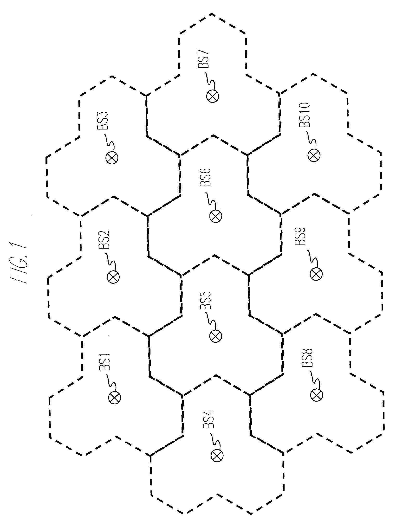
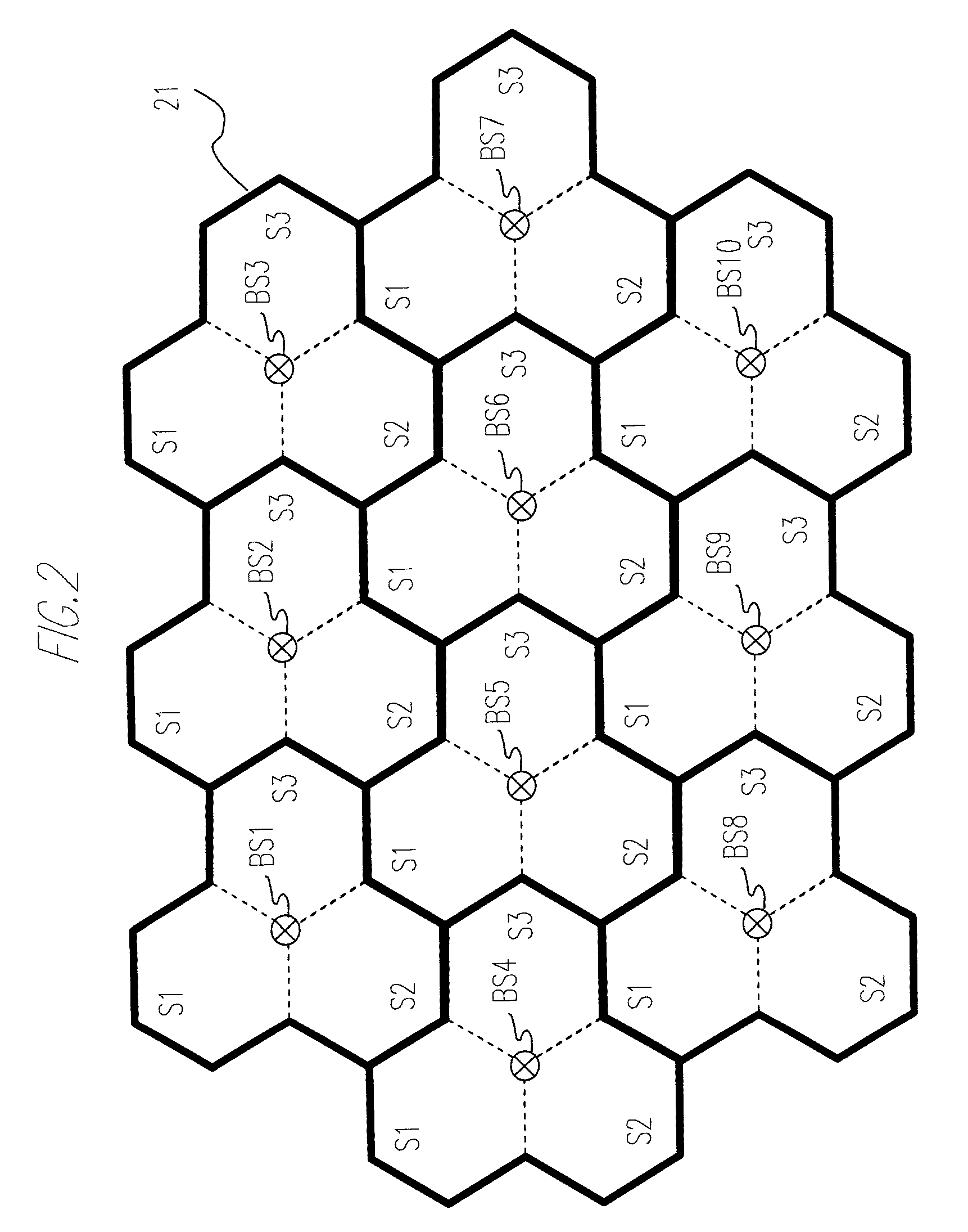
[0105]Each base station building up the FDMA cellular system in the embodiment uses the directional antennas, thereby forming the cells in which the small-cell 22 taking the 6-sector configuration, which does not abut on the cell of the neighboring base station, is put on the base cell 21 taking the 3-sector configuration of which the borders abut on the cell of the neighboring base station and in the internal peripheral area of the base station, respectively.

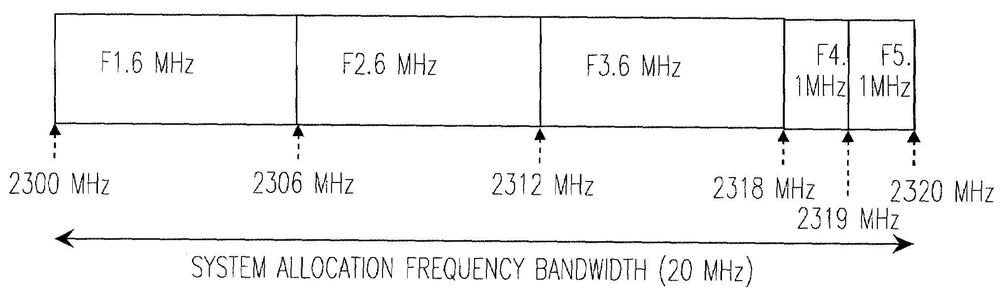
[0106]Then, the total frequency band allocated to each base station is divided by the minimum dividing count (the dividing count=5 in FIG. 4) so that with respect to the respective sector cells formed by the individual base stations, the frequency bands different from each other are allocated to the respective sector cells within the base cells 21, and the frequency bands, ...

modified examples

[0115]In the FDMA cellular system according to the embodiment discussed above, as illustrated in FIG. 2, each base cell 21 is configured by the three sector cells taking the hexagonal shape, however, another available configuration is that the base cell 21 taking the hexagonal shape on the whole, and the interior thereof is divided into three sector cells. FIG. 9 illustrates the cell configuration in this case. FIG. 9 is a diagram representing a first modified example of the cell configuration in the embodiment, and illustrates a frequency allocation of the frequencies F1 through F5.

[0116]Still another cell configuration is that the base cell 21 adopts the 6-sector configuration, while the small-cell 22 takes a 12-sector configuration. FIG. 10 is a diagram representing a second modified example of the cell configuration in the embodiment, and illustrates a frequency allocation of the frequencies F1 through F8. In this case also, with respect to the sector cells formed by each base s...


PUM


Abstract

A base station device includes a plurality of directional antennas, a power control unit and a frequency management unit. The cell is formed with layers of a base cell having a cell border with a cell formed by a neighboring base station device and including a plurality of sector cells and a small-cell having a cell radius smaller than a cell radius of the base cell and including at least four sector cells by the plurality of directional antennas and the power control unit. The frequency management unit manages frequency bands so that different frequency bands are allocated to the sector cells of the base cell, and a frequency band, which is different from the frequency bands allocated to the base cell and different between neighboring sector cells but the same between at least two sector cells, is allocated to each of the sector cells of the small-cell.

Description

CROSS-REFERENCE TO RELATED APPLICATIONS[0001]This is a continuation of Application PCT / JP2006 / 319478, filed on Sep. 29, 2006, now pending, the contents of which are herein wholly incorporated by reference.FIELD[0002]The present invention relates to a base station device building up a cellular system actualized by use of a wireless system such as FDMA and OFDMA required to take allocation of frequencies into consideration and to a cell forming method in the cellular system.[0003]As a cell configuration for covering a service target area without any blind area in a cellular system etc, there are a method of configuring an area by omni-cells using non-directional antennas and a method of configuring the area based on a sector configuration in which the cell is equally divided at a predetermined angle by using the directional antennas. As the sector configuration, three sector cells dividing the cell into three and six sector cells dividing the cell into six are general.[0004]In these c...

Claims


Application Information

Patent Timeline
Patent Type & Authority Applications(United States)
IPC IPC(8): H04W40/00H04M1/00H04W16/02H04W16/30H04W88/08
CPCH04W16/02H04W16/30H04W88/08H04W72/00H04W28/16
Inventor MATSUZAWA, HIROMU
Owner FUJITSU LTD
Why Eureka
Try Eureka