Floor scraper

Inactive Publication Date: 2009-07-30
AMERICAN SAFETY RAZOR CO
View PDF39 Cites 9 Cited by
  • Summary
  • Abstract
  • Description
  • Claims
  • Application Information

AI Technical Summary

Benefits of technology

[0006]An advantage of the present disclosure is an ergonomic floor scraper for easily and comfortably

Problems solved by technology

Having the wrong attack angle can damage the floor and hurt the user.
However, conventional designs do not allow the flexibility to afford all users an ideal attack angle.
Disadvantageously,

Method used


Image

  • Floor scraper
  • Floor scraper
  • Floor scraper

Examples


Example

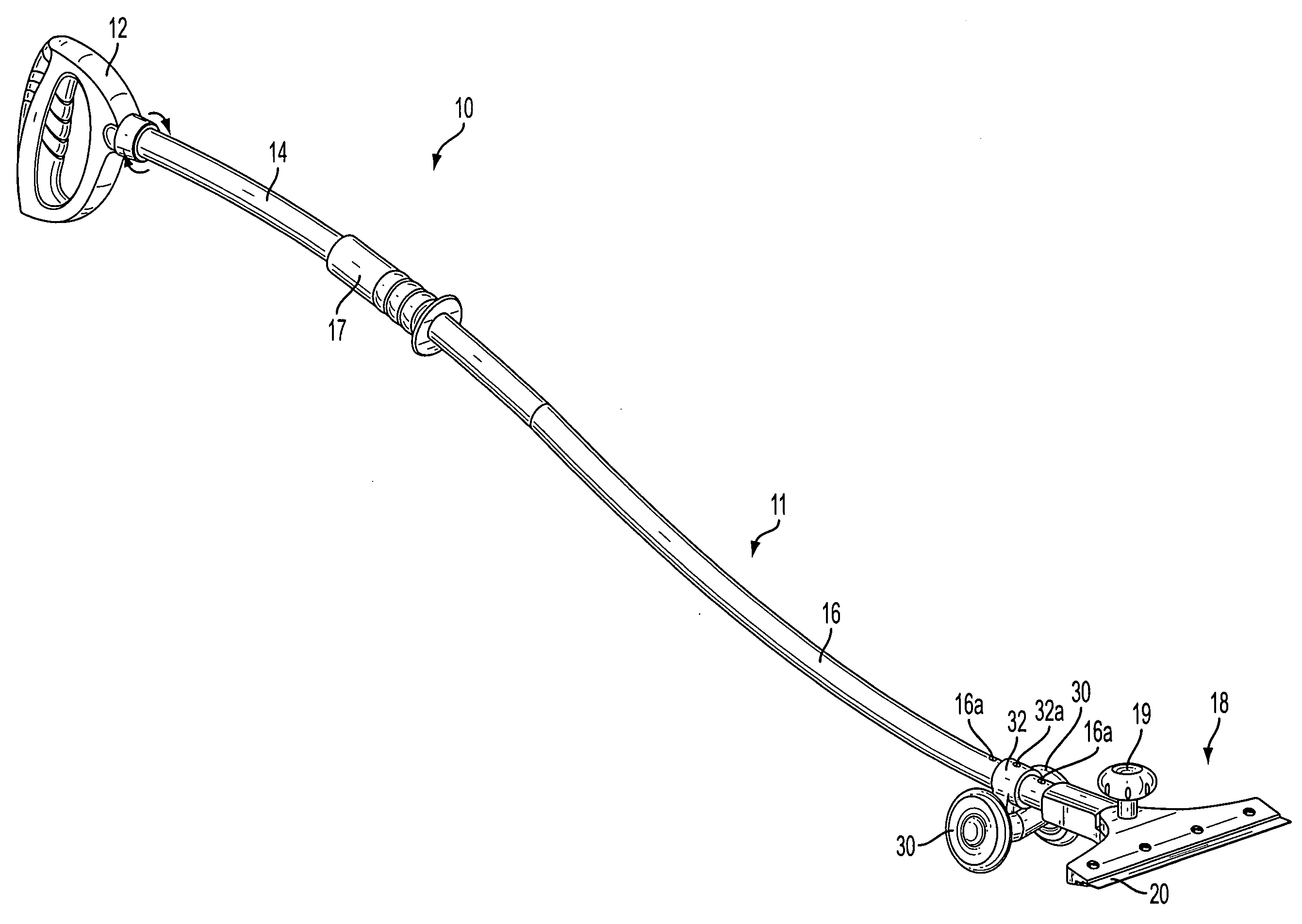
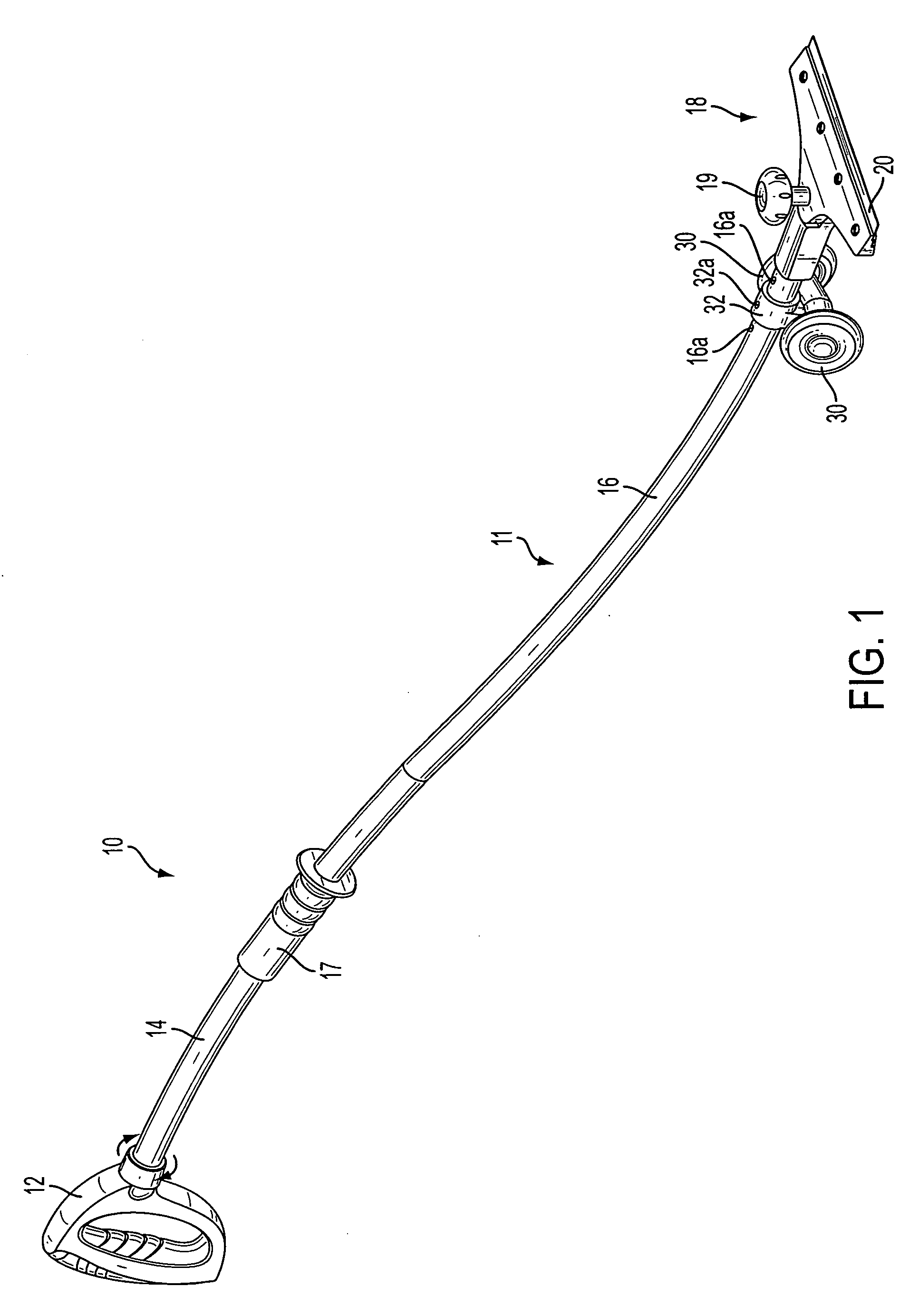
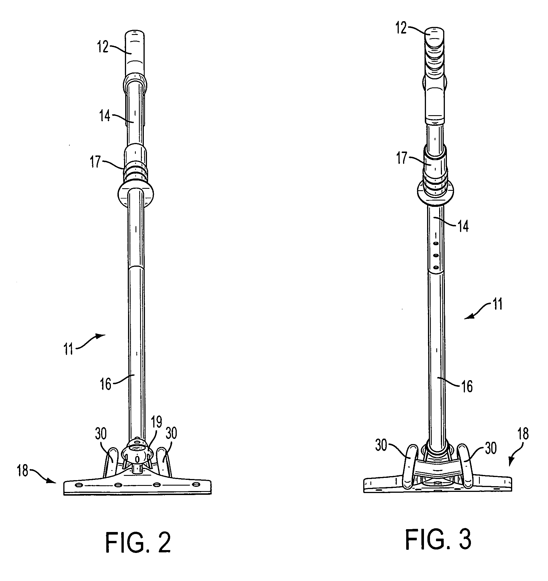
[0022]A floor scraper according to the present disclosure addresses the disadvantages of conventional floor scrapers, which are not ergonomically desirable, and have a head at a fixed angle to the handle. The present disclosure provides a scraper with and S-shaped handle and a set of wheels for easily and comfortably adjusting the blade attack angle, and an adjustable scraper head whose blade angle with respect to the handle can be changed to suit the user and / or the job. The scraper of the present disclosure also has textured grips for both the user's hands, for better control.

[0023]One embodiment of the present disclosure shows a floor scraper 10 having an “S” shaped handle 11 to reduce the scraper attack angle and decrease the amount of bending required. Handle 11 includes an upper hand grip 12, an upper handle element 14, a lower hand grip 17, a lower handle element 16, and a scraper head 18. The handle 11 is made of the two identical curved handle elements 14, 16 and is connect...


PUM


Abstract

An ergonomic scraper, such as a floor scraper using a standard replaceable blade, is provided. Embodiments include a scraper having an elongated handle, a scraper head for fixedly holding a blade mounted to a first end of the handle, an upper hand grip at a second end of the handle, and a lower hand grip between the first and second ends of the handle. The handle has an S-shape to reduce the angle between the blade and a workpiece. A pair of wheels is mounted near the scraper head for easily adjusting the blade attack angle. The scraper head is adjustable for changing the scraping angle of the blade to suit the user and/or the job.

Description

RELATED APPLICATION[0001]The present invention claims priority of provisional patent application No. 61 / 006,753 filed Jan. 30, 2008, the contents of which are incorporated herein in their entirety.TECHNICAL FIELD[0002]The present disclosure relates to a scraper. The present disclosure has particular applicability to floor scrapers with replaceable blades.BACKGROUND[0003]Floor scrapers, also called floor strippers, are used to remove tile, glue, etc. from floors. Present floor scrapers consist of a straight steel tube handle with rubber hand grips around it. At the working end, the tube is connected to a metal housing, known as a scraper head, holding a scraper blade. A typical conventional design uses a standard replaceable blade, such as an 8″ scraper blade, held in place to a head by screws and a flat plate that mates with the head.[0004]The attack angle of the blade is dependent on the height of the user at the end of the tube and / or the amount that the user is bent over. Having ...

Claims


Application Information

Patent Timeline
IPC IPC(8): B26B3/00
CPCA47L13/022E04G23/006A47L13/08
Inventor VAN DEURSEN, GARY E.KAISER, DAVID W.JOHNSON, LUKE
Owner AMERICAN SAFETY RAZOR CO
Why Eureka
Try Eureka