Blanking die apparatus and method for manufacturing laminated iron core

Active Publication Date: 2015-07-02
MITSUI HIGH TEC INC
View PDF0 Cites 0 Cited by
  • Summary
  • Abstract
  • Description
  • Claims
  • Application Information

AI Technical Summary

Benefits of technology

The present invention relates to a non-limited object of providing a blanking die apparatus that prevents sheets from getting caught in the lower die or residue of the sheet during a feeding operation. This improves the productivity and quality of laminated iron cores. The invention achieves this by reducing the lifting height of the second lifter, which reduces the own weight of the sheet and prevents mechanical damage. As a result, this prevents the sheet from being caught and improves the quality of the laminated iron core.

Problems solved by technology

Further, a problem also arises that dents are generated in the laminated iron core (a product) by residue of the sheet generated by the mechanical damage.

Method used


Image

  • Blanking die apparatus and method for manufacturing laminated iron core
  • Blanking die apparatus and method for manufacturing laminated iron core
  • Blanking die apparatus and method for manufacturing laminated iron core

Examples


Embodiment Construction

[0032]Subsequently, by referring to the attached drawings, an exemplary embodiment which embodies the present invention will be described to understand the present invention.

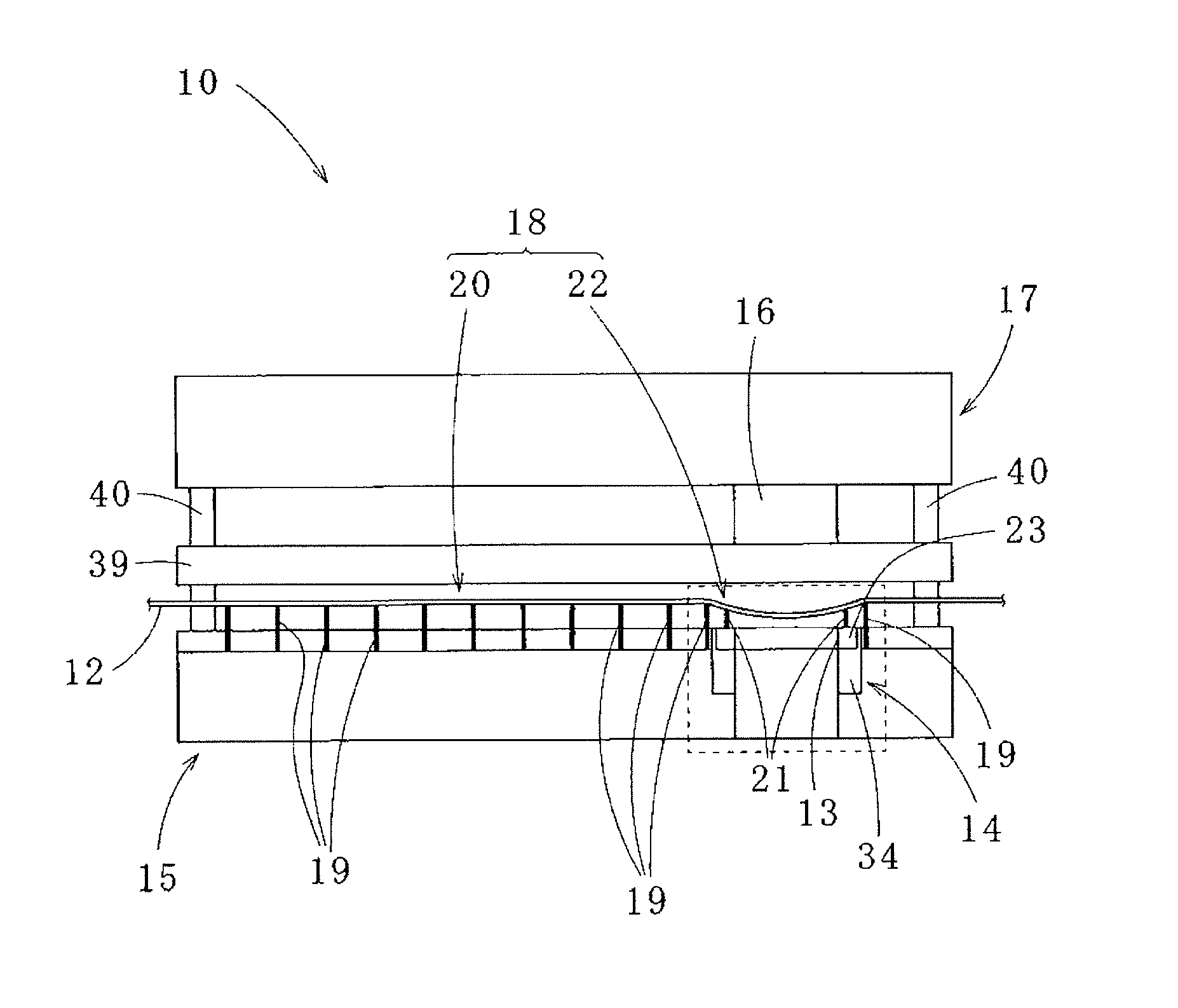
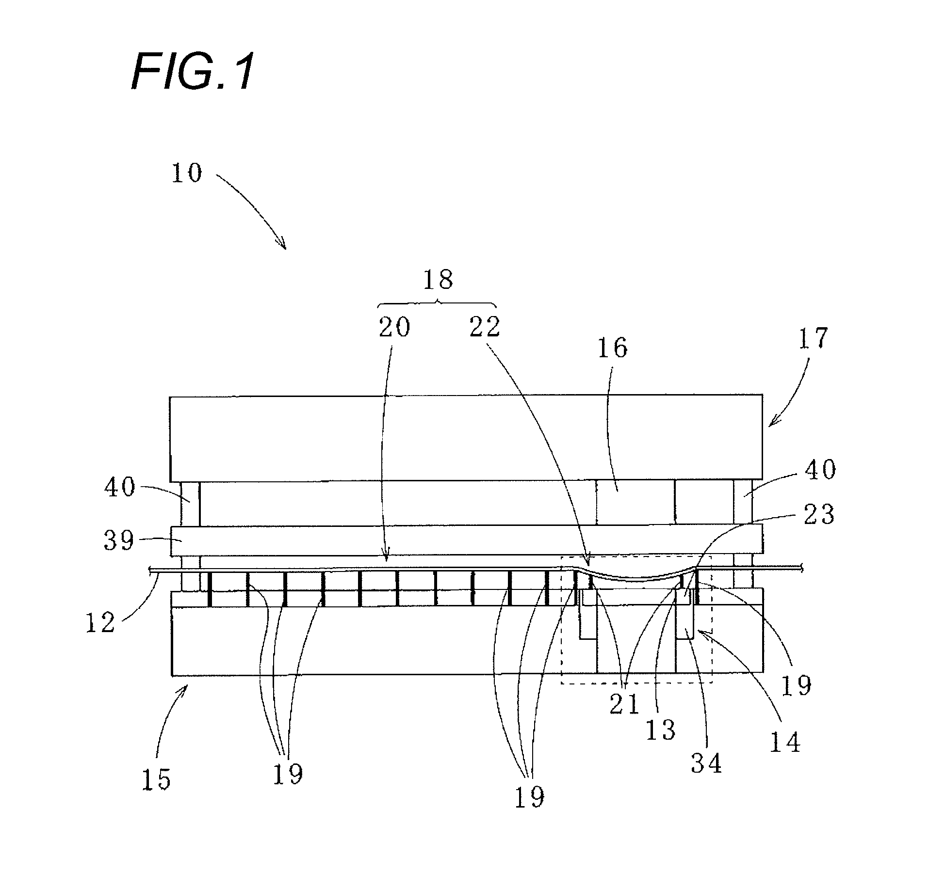
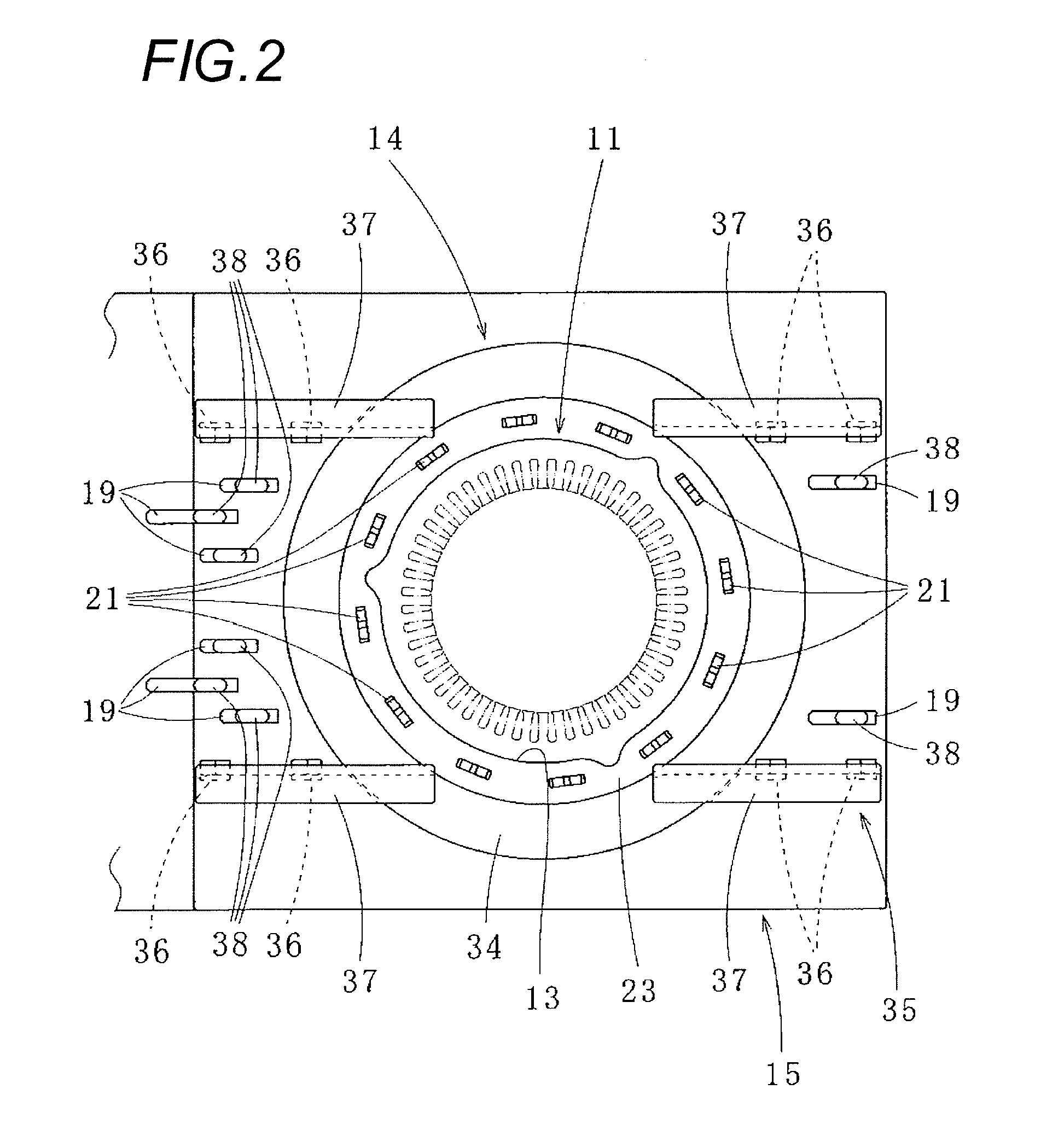
[0033]As shown in FIG. 1, a blanking die apparatus 10 according to one exemplary embodiment of the present invention includes a lower die 15 in which are arranged a plurality of working stations (not shown in the drawing) for forming patterns respectively having blanking holes which form the patterns of iron core pieces 11 (see FIG. 2) that form a laminated iron core by sequentially carrying out a blanking or stamping work on a belt shaped sheet 12 and a working station 14 of a final stage including a blanking hole 13 for blanking in the external form that blanks areas where the patterns are completed from the sheet 12 in the external forms to form the iron core pieces 11. Further, the blanking die apparatus 10 includes an upper die 17 which moves upward and downward with respect to the lower die 15 and is oppos...


PUM

PropertyMeasurementUnit
Widthaaaaaaaaaa
Areaaaaaaaaaaa
Heightaaaaaaaaaa

Abstract

A blanking die apparatus includes a lower die in which a plurality of working stations are arranged, and an upper the which moves upward and downward with respect to the lower die. A progressively fed sheet is sequentially blanked or stamped out respectively in the working stations to form iron core pieces, and then to laminate the iron core pieces to form a laminated iron core. The lower die includes a lifter part which lifts the sheet from the lower die when the sheet is progressively fed. The lifter part first lifters installed in an outer peripheral area in each of the working stations, and second lifters installed on an upper surface of a blank die which has a blanking hole formed for blanking the iron core pieces in an external form, or on an upper surface of a blank die holder.

Description

CROSS REFERENCE TO RELATED APPLICATIONS[0001]This application is based upon and claims the benefit of priority of Japanese Patent Application No. 2013-269181 filed on Dec. 26, 2013, the contents of which are incorporated herein by reference in its entirety.BACKGROUND OF THE INVENTION[0002]1. Field of the Invention[0003]The present invention relates to a blanking die apparatus which blanks iron core pieces from a progressively fed sheet to form a laminated iron core and a method for manufacturing the laminated iron core by using the blanking die apparatus.[0004]2. Description of the Related Art[0005]For instance, a laminated iron core which forms a stator or a rotor of a motor is manufactured as follows. A belt-shaped sheet such as an electromagnetic steel plate is progressively fed to a blanking die apparatus, sequentially blanked or stamped out in working stations respectively arranged along a feeding direction of the sheet to form iron core pieces of desired forms and the obtained...

Claims


Application Information

Patent Timeline
IPC IPC(8): H01F41/02H02K15/02B21D28/06
CPCH01F41/0233H02K15/02B21D28/06B21D28/22H02K15/024Y10T29/49078Y10T29/5142
Inventor YAMATO, SHIGETOSHI
Owner MITSUI HIGH TEC INC
Why Eureka
Try Eureka