Post-combustion lance with internal support

Active Publication Date: 2009-07-30
A H TALLMAN BRONZE
View PDF13 Cites 13 Cited by
  • Summary
  • Abstract
  • Description
  • Claims
  • Application Information

AI Technical Summary

Benefits of technology

[0014]In its broad aspect, the invention provides a post-combustion lance for directing a gas at least partially therethrough. The post-combustion lance includes a body extending between an upstream end and a downstream end of the lance, the upstream end being adapted to receive the gas, and the downstream end comprising a primary tip through which a first part of the gas exits the lance. The body includes upper and lower portions and a post-combustion distributor mounted therebetween at a predetermined distance from the primary tip. The distributor includes a number of ports through which a second part of the gas exits the lance. The lance also includes an upper inner tube positioned at least partially upstream from the distributor attached to the upper portion, and a lower inner tube positioned at least partially downstream from the distributor attached to the lower portion. In addition, the lance includes an internal support assembly for supporting the body. The internal support assembly includes an internal tube positioned inside the body and at least partially upstream relative to the lower inner tube. The internal tube is engaged with the lower inner tube. Also, the assembly includes one or more collars positioned between the upper inner tube and the internal tube, to support the internal tube in a predetermined position coaxial with the body so that the internal tube resists deflection of the body.
[0015]In another of its

Problems solved by technology

Lances equipped with the PC distributor typically are prone to severe bending (i.e., deflection) and, in some cases, failure at the PC distributor, because of the relatively low yield strength of the high thermal conductivity components in the PC distributor.
Since the introduction of the mid-lance PC distributor (i.e., at least in the 1980s, and possibly earlier), no effective solutions to the bending and/or failure probl

Method used


Image

  • Post-combustion lance with internal support
  • Post-combustion lance with internal support
  • Post-combustion lance with internal support

Examples


Example

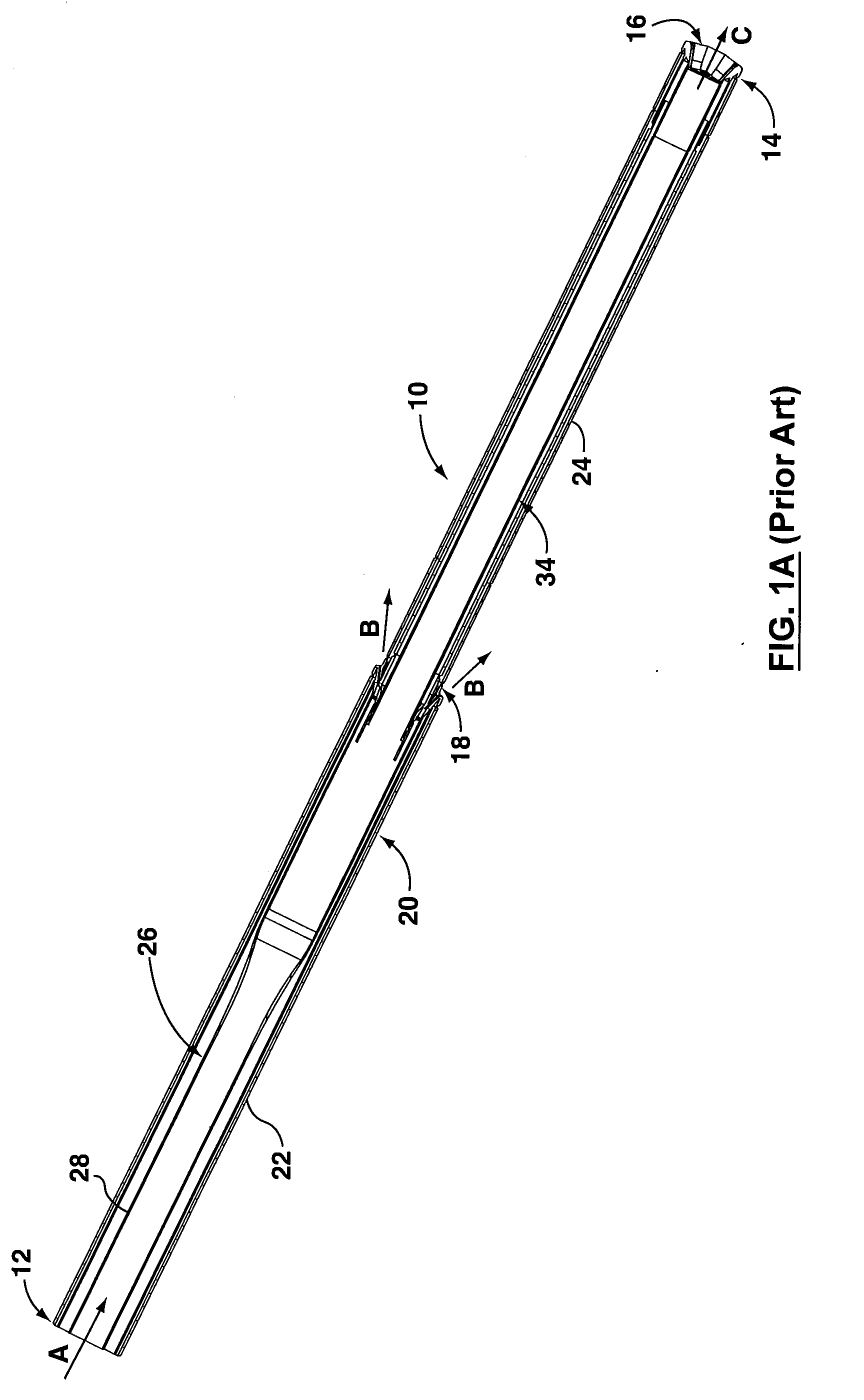
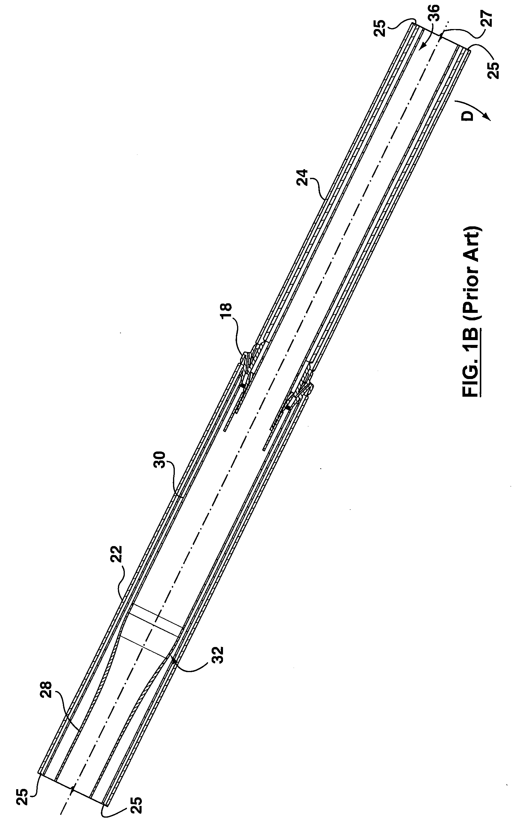
[0044]To simplify the description, the reference numerals used previously in FIGS. 1A and 1B will be used again in connection with the description of the invention hereinafter, except that each such reference numeral is raised by 100 (or by whole number multiples thereof, as the case may be), where the parts described correspond to parts described above.

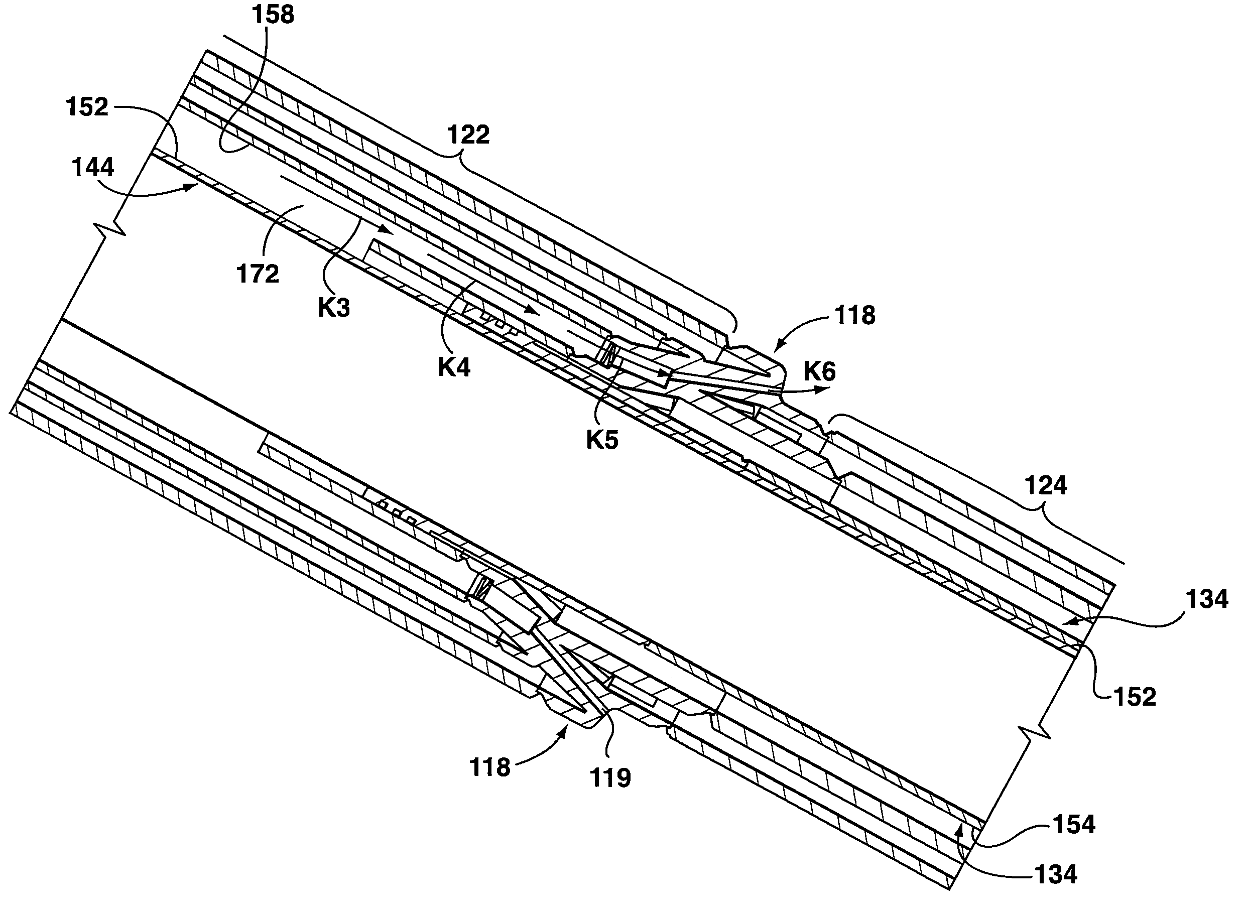
[0045]Reference is first made to FIGS. 2A-2E and 6A-6C to describe an embodiment of a post-combustion lance in accordance with the invention indicated generally by the numeral 140. The post-combustion lance 140 is for directing a gas (not shown) at least partially therethrough. In one embodiment, the post-combustion lance 140 includes a body 120 extending between an upstream end 112 and a downstream end 114 of the lance 140. The upstream end 112 is adapted to receive the gas, and the downstream end 114 includes a primary tip 116 through which a first part of the gas exits the lance 140. The body 120 also includes upper and lower port...


PUM

PropertyMeasurementUnit
Flow rateaaaaaaaaaa
Diameteraaaaaaaaaa

Abstract

A post-combustion lance for directing a gas at least partially therethrough. The post-combustion lance includes a body having a primary tip from which a first part of the gas exits, upper and lower portions, and a post-combustion distributor mounted between the upper and lower portions and upstream from the primary tip. The distributor includes a number of ports through which a second part of the gas exits the lance. The lance also includes an upper inner tube positioned at least partially upstream from the distributor and an internal support assembly for supporting the body. The internal support assembly includes an internal tube positioned inside the body and coaxial with the body.

Description

[0001]This application claims the benefit of U.S. Provisional Application No. 61 / 023,275, filed on Jan. 24, 2008, which is hereby incorporated by reference in its entirety.FIELD OF THE INVENTION[0002]This invention is related to a post-combustion lance with a body including an internal support assembly for supporting the body.BACKGROUND OF THE INVENTION[0003]Metallurgical processes such as basic oxygen steelmaking often employ large (typically, about 8 inches to about 16 inches in diameter and approximately 65-85 feet long) water-cooled oxygen lances to efficiently remove oxidizable elements from molten metal in a metallurgical converter. These lances, which typically weigh up to approximately 10 tons, are known as post-combustion lances. Typically, in addition to the primary oxygen ports at the tip of the lance, the prior art post-combustion lance includes a ring of small oxygen ports located on the outside of the lance a distance up the lance from the primary oxygen tip. The ring ...

Claims


Application Information

Patent Timeline
IPC IPC(8): C21C5/30
CPCC21C5/30C21C5/305F27D3/16C21C5/462F23C2900/07021C21C5/4606
Inventor STRELBISKY, MICHAEL J.LEGEARD, KERRY J.WHYTE, WILLIAM D.
Owner A H TALLMAN BRONZE
Why Eureka
Try Eureka