Single-bolt band clamp with gasketed center rib and pipe lap joint using the same

a single-bolt, gasketed technology, applied in the direction of hose connection, machine/engine, mechanical apparatus, etc., can solve the problems of pipe end connection still being adversely affected, loss of gas tightness at the joint,

Active Publication Date: 2009-07-30
NORMA US HOLDING LLC
View PDF40 Cites 32 Cited by
  • Summary
  • Abstract
  • Description
  • Claims
  • Application Information

AI Technical Summary

Benefits of technology

[0006]One aspect of the invention is directed to a band clamp that connects a first and second pipe end in an overlapping configuration. The band clamp includes a band, a tightening mechanism, and a gasket. The band extends circumferentially from a first end to a second end, and extends axially between a pair of axial ends. The band includes a radially protruding rib that extends circumferentially part way or more between the first and second ends and that is located inwardly of the axial ends. The band further includes a first lateral section that extends from a side of the rib, and includes a second lateral section that extends from a side of the rib opposite the first lateral section. Each of the first and second lateral sections has an axial width with a value within a range of about 50 to 150 percent of an axial width of the rib. The tightening mechanism is connected to the band and brings the first and second ends toward each other in order to tighten the band. The gasket is located in a radial direction beneath the band, and in an axial direction within or greater than the rib.
[0007]Another aspect of the invention is directed to a band clamp that connects a first and second pipe end in an overlapping configuration. The band clamp includes a band, a tightening mechanism, and a gasket. The band extends circumferentially from a first end to a second end, and extends axially between a pair of axial ends. The band includes a radially protruding rib that extends circumferentially part way or more between the first and second ends and that is located inwardly of the axial ends. The band further includes a first lateral section that extends from a side of the rib, and includes a second lateral section that extends from a side of the rib opposite the first lateral section. Each of the first and second lateral sections is angled in a radially inward direction with respect to an axis of the band at an angle hav...

Problems solved by technology

Where a clamped joint does not have sufficient stiffness, these bending moments can be responsible for a loss of a gas-tightness at the joint which, for automotive exhaust and various other applications, can be undesirable.
However, the pipe end connection can still be adversely affec...

Method used


Image

  • Single-bolt band clamp with gasketed center rib and pipe lap joint using the same
  • Single-bolt band clamp with gasketed center rib and pipe lap joint using the same
  • Single-bolt band clamp with gasketed center rib and pipe lap joint using the same

Examples


Embodiment Construction

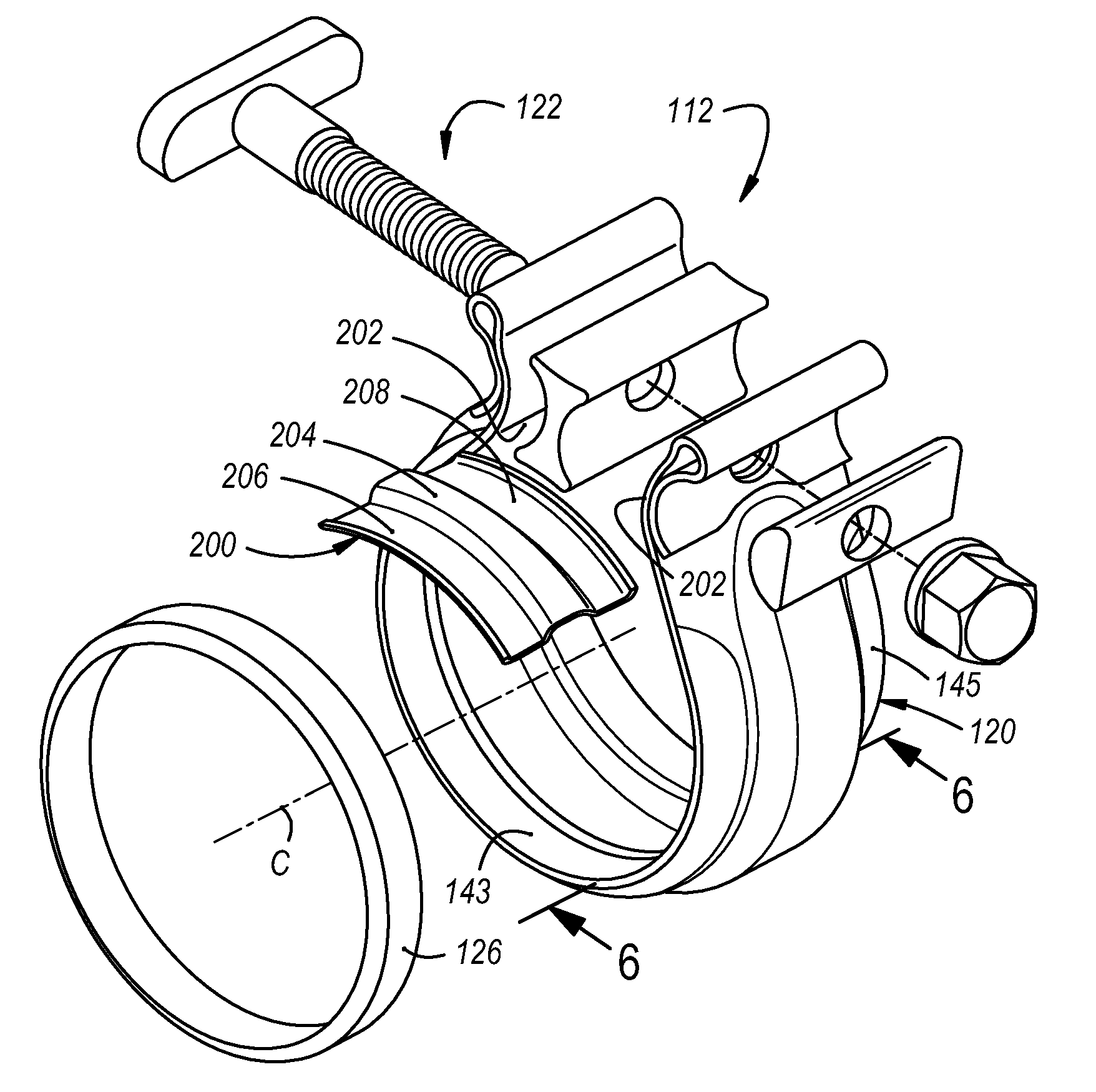
[0016]As used herein, the terms axially, angularly, and radially refer to directions relative to the cylindrically tubular shape of the illustrated pipes and band clamp, so that the axial direction extends along the axis of this tubular shape, radial directions extend radially away from this axis, and angularly refers to locations at points around the circumference of the band clamp.

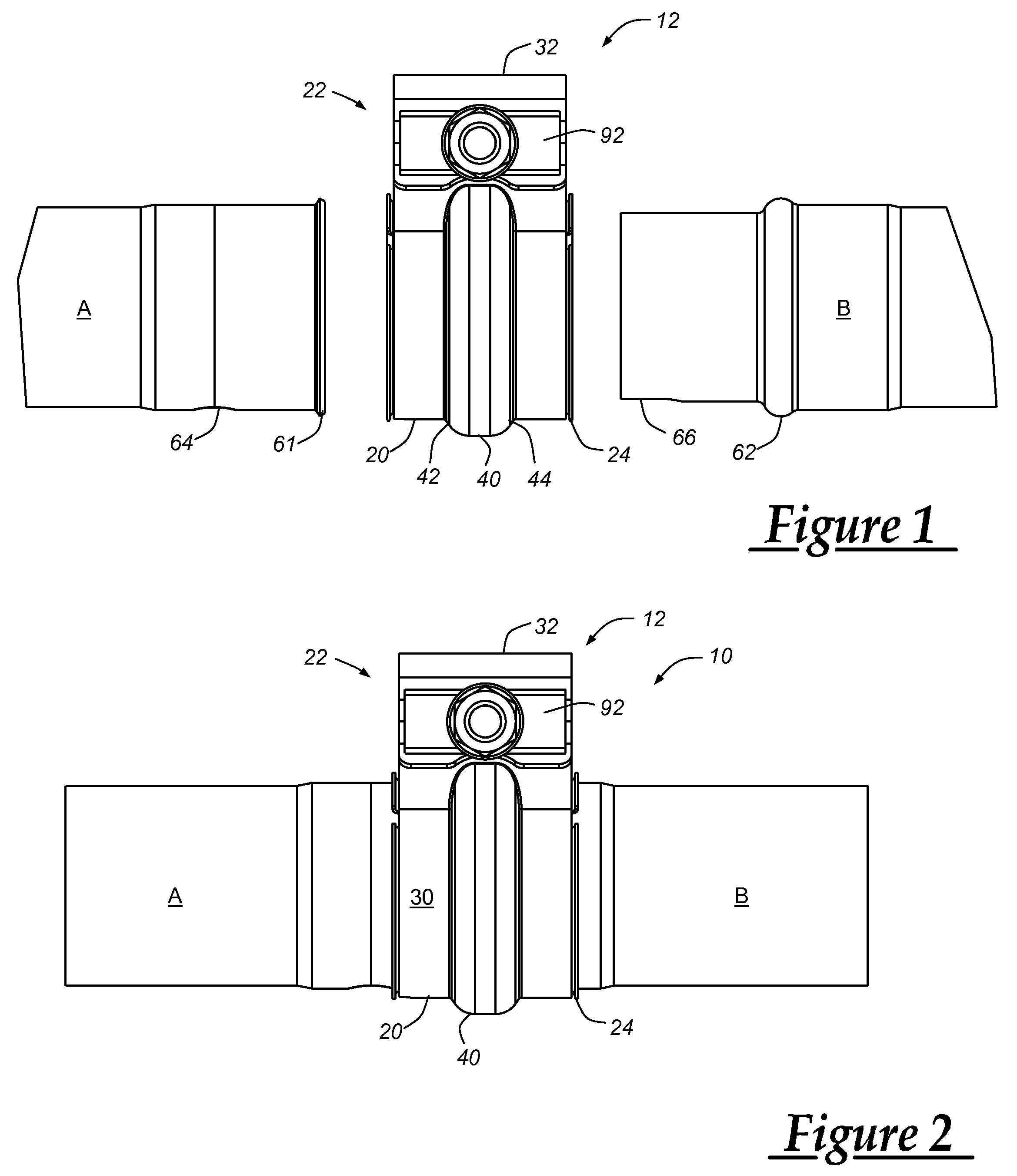
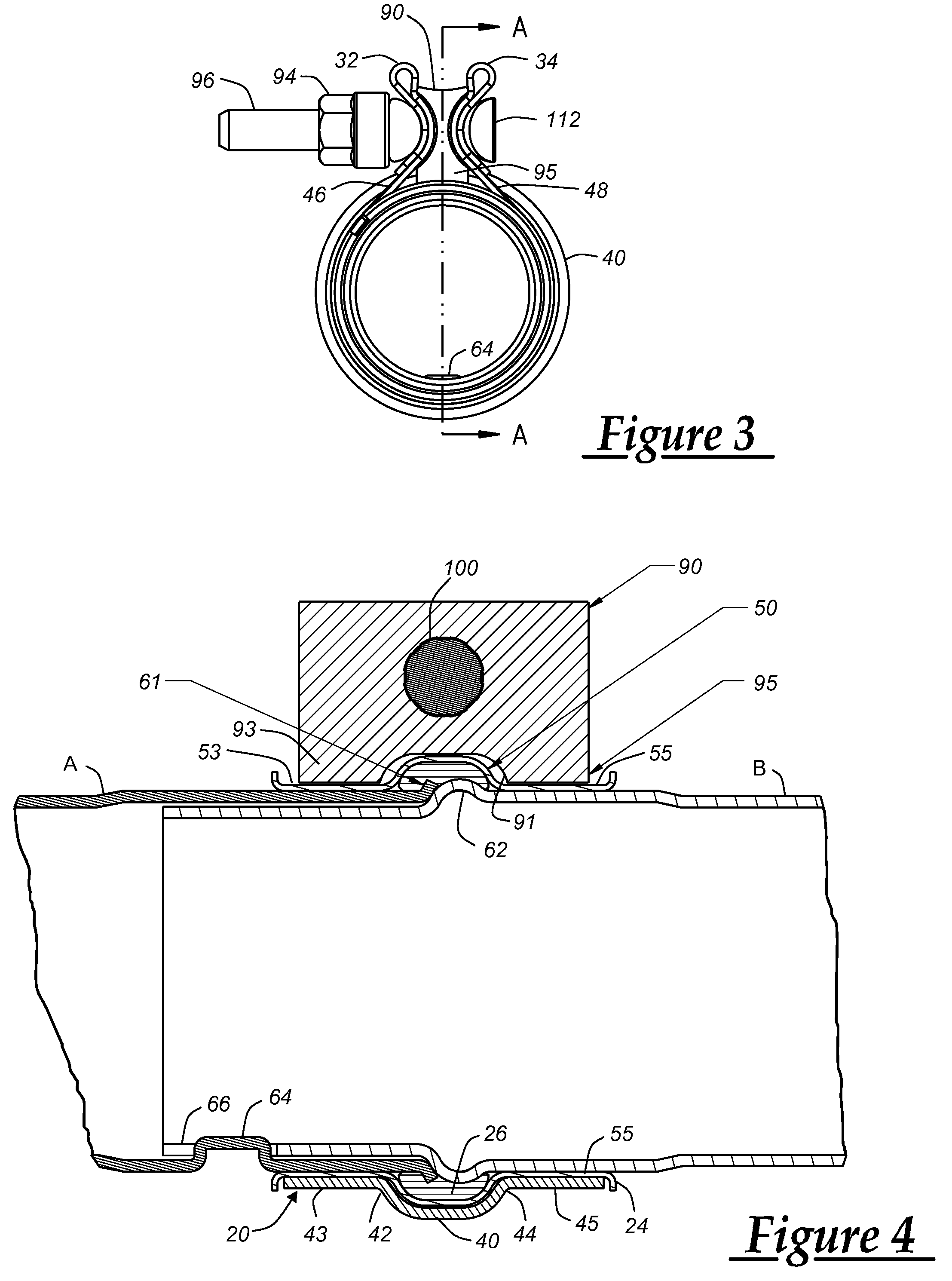
[0017]FIGS. 1-4 depict a band clamp 12 and overlapping ends of two pipes A and B that together are assembled as shown in FIGS. 2-4 into a clamped pipe joint 10. In general, the joint 10 is formed by placing the clamp 12 loosely over one pipe end (e.g., over the end of pipe A), inserting the other pipe end through the clamp and into an overlapping position relative to the first pipe end, and then tightening the clamp to secure the two pipes A and B together.

[0018]Band clamp 12 includes the same general components disclosed in U.S. Patent Application Publication No. 2006 / 0175837 A1 in connection with the b...


PUM


Abstract

A band clamp that connects overlapping pipe ends includes a band, a tightening mechanism, and a gasket. The band has a radially protruding rib, a first lateral section that extends from a side of the rib, and a second lateral section that extends from another side of the rib. The tightening mechanism connects to the band and is operable to tighten the band, and the gasket is received in the rib. In one example, an axial width of the lateral sections are within a range relative to an axial width of the rib, and in another example, the lateral sections are angled inwardly with relative to an axis of the band.

Description

CROSS-REFERENCE TO RELATED APPLICATIONS[0001]This application claims the priority of U.S. Provisional Patent Application No. 61 / 024,752, filed Jan. 30, 2008, the complete disclosure of which is hereby incorporated by reference.TECHNICAL FIELD[0002]This invention relates to pipe clamps and more particularly to band clamps used to secure pipe ends in a lap joint configuration.BACKGROUND OF THE INVENTION[0003]United States Patent Application No. 2006 / 0175837 A1 discloses various embodiments of a pipe clamp having a gasketed center rib that can be used to clamp and seal a pair of ribbed pipe ends. One of the disclosed pipe clamp embodiments (FIGS. 1-4) is in the form of a one-bolt band clamp that can be used for telescopic pipe connections in which one pipe end fits into the other pipe end in an overlapping configuration. Such telescopic connections of the pipe ends are also referred to as a lap joint. These band clamps often can use only a single bolt, with the clamping force from tigh...

Claims


Application Information

Patent Timeline
IPC IPC(8): F16L25/00
CPCF16L21/065F01N13/1805F16L21/08F16L33/04
Inventor IGNACZAK, BRIAN T.
Owner NORMA US HOLDING LLC
Why Eureka
Try Eureka