Antenna device and radio apparatus operable in multiple frequency bands
a radio apparatus and antenna technology, applied in the direction of elongated active element feed, resonance antenna, antenna earthing, etc., can solve the problems of difficult to excite the parasitic element at a desired frequency, difficult to shape the radio apparatus including the elements as a built-in antenna into a low profile configuration, and may disturb the broadband characteristic of parallel resonan
- Summary
- Abstract
- Description
- Claims
- Application Information
AI Technical Summary
Benefits of technology
Problems solved by technology
Method used
Image

Examples
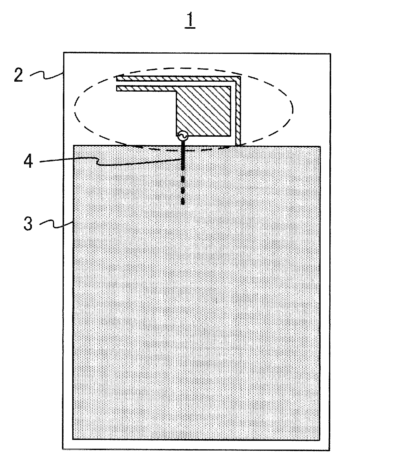
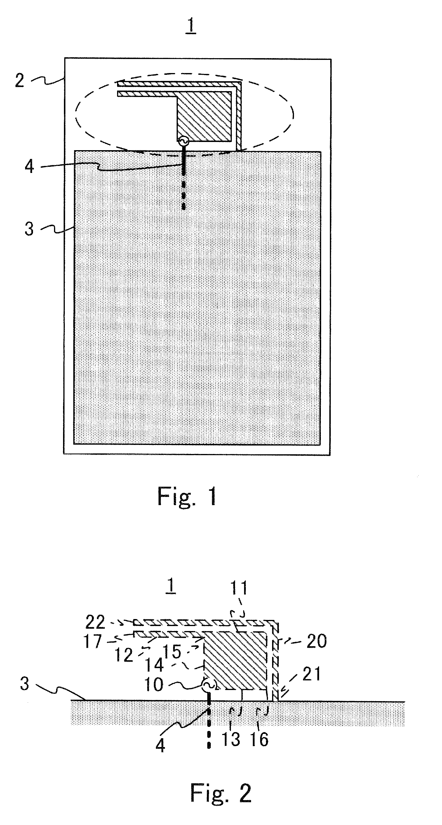
first embodiment
[0073]The antenna device 1 may avoid such a problem by assigning the lowest resonant frequency to the parasitic element 20. The antenna device 1 may implement a resonant frequency at least higher than F4 by using a third harmonic of F5 (=3XF5) so as to further broaden the frequency characteristic in a higher frequency range. An effect of the first embodiment in a broadband aspect will be specifically described later with reference to FIGS. 6-12.
[0074]The open end 22 is arranged close to the end 17 of the second partial element 12 as described above, and may be voltage-coupled to the end 17 if the antenna device 1 is fed at the feed portion 10. It is necessary to make a distance between the open end 22 and the end 17 small enough to ensure the voltage-coupling.
[0075]If the open end 22 is located relatively to the end 17 in a direction parallel to thickness of a housing section of the radio apparatus including the antenna device 1, the above small distance may secondarily contribute t...
second embodiment
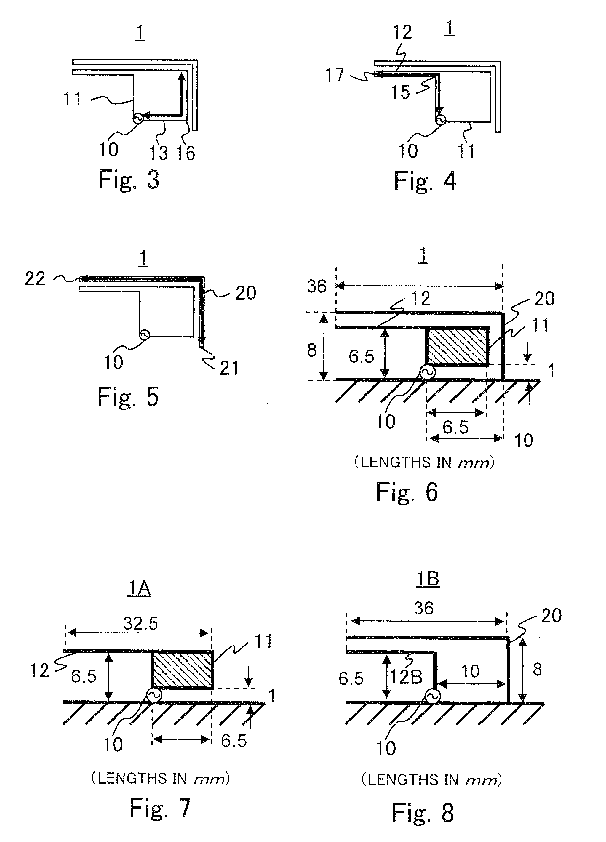
[0120]the present invention will be described with reference to FIGS. 22-41. The second embodiment includes plural modifications of each of the portions of the antenna device 1 of the first embodiment. Each of the modifications will be described with an associated drawing.
[0121]For convenience of explanation, each of main portions of each of the modifications is given a same reference numeral as the corresponding one of the first embodiment, such as the ground conductor 3, the feed portion 10, the first partial element 11, the second partial element 12, and the parasitic element20 and so on.
[0122]FIG. 22 is a plan view of a modification including an additional parasitic element 40 added to the antenna device 1. The additional parasitic element 40 has an end grounded around the feed portion 10 and another end being open. The additional parasitic element 40 may be current-coupled to the left side portion of the first partial element 11 and has a resonant frequency determined by an ele...
PUM
 Abstract
Description
Claims
Application Information
 - R&D Engineer
- R&D Manager
- IP Professional
- Industry Leading Data Capabilities
- Powerful AI technology
- Patent DNA Extraction
Browse by: Latest US Patents, China's latest patents, Technical Efficacy Thesaurus, Application Domain, Technology Topic.
© 2024 PatSnap. All rights reserved.Legal|Privacy policy|Modern Slavery Act Transparency Statement|Sitemap