Light meter apparatus and system

a light meter and light meter technology, applied in the field of light meter apparatus and system, can solve the problems of affecting the health and well-being of humans, affecting the accuracy or usability of real-life situations of measurement in the field environment, and reducing the quality of life, so as to achieve the effect of easy identification

Active Publication Date: 2009-07-30
UL
View PDF15 Cites 9 Cited by
  • Summary
  • Abstract
  • Description
  • Claims
  • Application Information

AI Technical Summary

Benefits of technology

[0022]When using a conventional telephotometer, or a telescopic spot meter, to measure distant sources, that has a narrow field of view, it can be difficult for the operator to find the light source when sighting through the telephotometer. It is therefore desirable for the telephotometer to have a variable field of view. In a first setting of the telephotometer presented in

Problems solved by technology

Today light intensity is only measured in laboratory settings and translation of such measurement to real life situations in the field environment is not as accurate or usable as is desired.
If light energy or light rays emitted by light fixtures illuminate areas outside of that area which they are intended to light, the light is considered to be “spillover light,” or “trespass light.” Spillover light, in residential neighborhoods, disturbs the tranquility of th

Method used


Image

  • Light meter apparatus and system
  • Light meter apparatus and system
  • Light meter apparatus and system

Examples


Embodiment Construction

[0046]In the following description, and for the purposes of explanation, numerous specific details are set forth in order to provide a thorough understanding of the various aspects of the invention. It will be understood, however, by those skilled in the relevant arts, that the present invention may be practiced without these specific details. In other instances, known structures and devices are shown or discussed more generally in order to avoid obscuring the invention. In many cases, a description of the operation is sufficient to enable one to implement the various forms of the invention, particularly when the operation is to be implemented in software. It should be noted that there are many different and alternative configurations, devices and technologies to which the disclosed inventions may be applied. The full scope of the inventions is not limited to the examples that are described below.

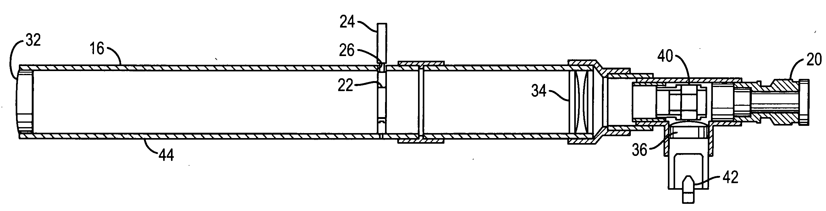
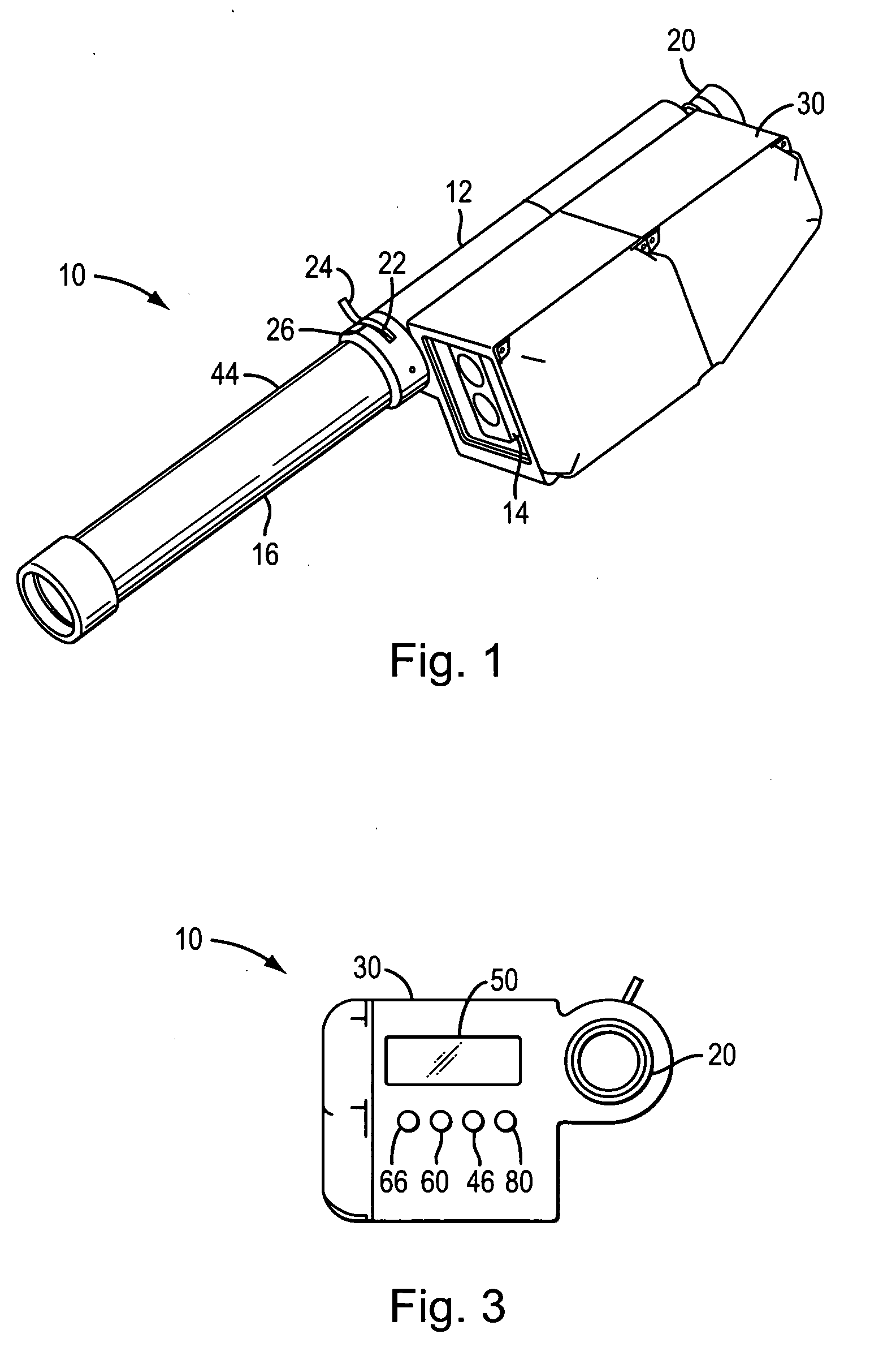
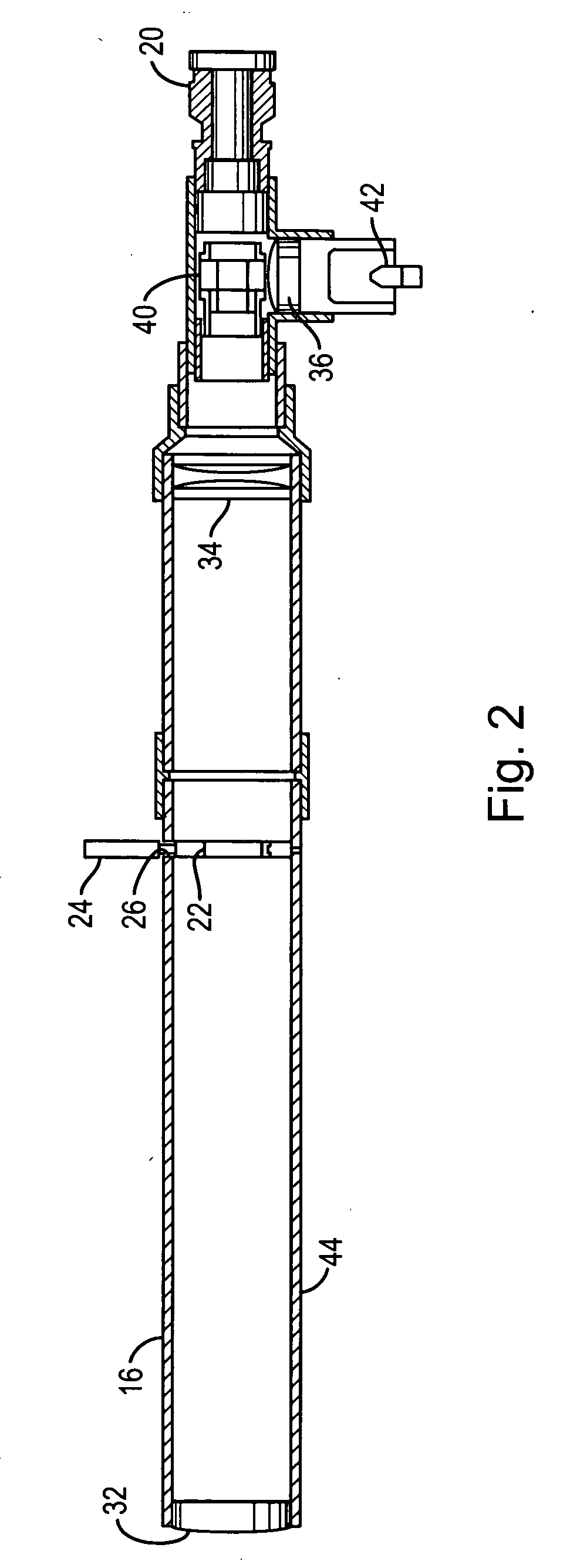
[0047]In one embodiment of the invention the light measuring apparatus comprises a tele...


PUM


Abstract

A light meter for measuring photometric quantities includes a telephotometer having a photo detector to receive light energy entering the telephotometer. A light metering valve, for the purpose of providing a variable field of view, is located in the body of the telephotometer generally at the focal plane of the objective lens of the telephotometer. A controller, which includes a digital processor in communication with the photo detector will process information from the photo detector and from a range finder included in the system to output light intensity of a target light source.

Description

BACKGROUND OF THE INVENTION[0001]1. Field of the Invention[0002]This invention is related to a device, and a method of using the device, that is used to measure various photometric quantities of the light emanating from a light source. Generally a light source, particularly an exterior light source, is configured and positioned to cast light in a desirable pattern. Often the light source will indiscriminately emit light such that the some of the emitted light is directed beyond the intended lighted zone. Light extending beyond the targeted object of the lighting system is “spillover.” When spillover extends beyond property lines it is known as “trespass light” and may be objectionable to people subjected to this intrusive trespass light.[0003]The device presented in this disclosure measures the light from a distant light source. The distant light source may be the source of spillover light, trespass light and a source of glare. The measurement of spillover and trespass light is the ...

Claims


Application Information

Patent Timeline
IPC IPC(8): G01C3/08G01J1/42
CPCG01J1/02G01J1/0219G01J1/0228G01J1/0242G01J1/0266G01J1/08G01J1/0411G01J1/0437G01J1/0448G01J1/0466G01J1/04
Inventor LEWIN, IANO'FARRELL, JOHN K.DOMIGAN, JAMES L.
Owner UL
Why Eureka
Try Eureka