Optical lens arrangement for fixed lenses and a liquid lens

a liquid lens and fixed lens technology, applied in the field of optical lens arrangement, can solve the problems of difficult to add more fixed lenses to the system, and difficulty in maintaining an acceptable level of alignment between fixed lenses

Inactive Publication Date: 2009-07-30
VARIOPTIC SA
View PDF7 Cites 40 Cited by
  • Summary
  • Abstract
  • Description
  • Claims
  • Application Information

AI Technical Summary

Benefits of technology

[0010]It is an aim of embodiments of the present invention to at

Problems solved by technology

This poses the problem of how to align the fixed lenses with each other, and with the liquid interface.
A drawback with the lens arrangement of FIG. 2 is that it is very difficult to maintain an acceptable level of accuracy in the alignment between the fixed lenses due to the numer

Method used


Image

  • Optical lens arrangement for fixed lenses and a liquid lens
  • Optical lens arrangement for fixed lenses and a liquid lens
  • Optical lens arrangement for fixed lenses and a liquid lens

Examples


Embodiment Construction

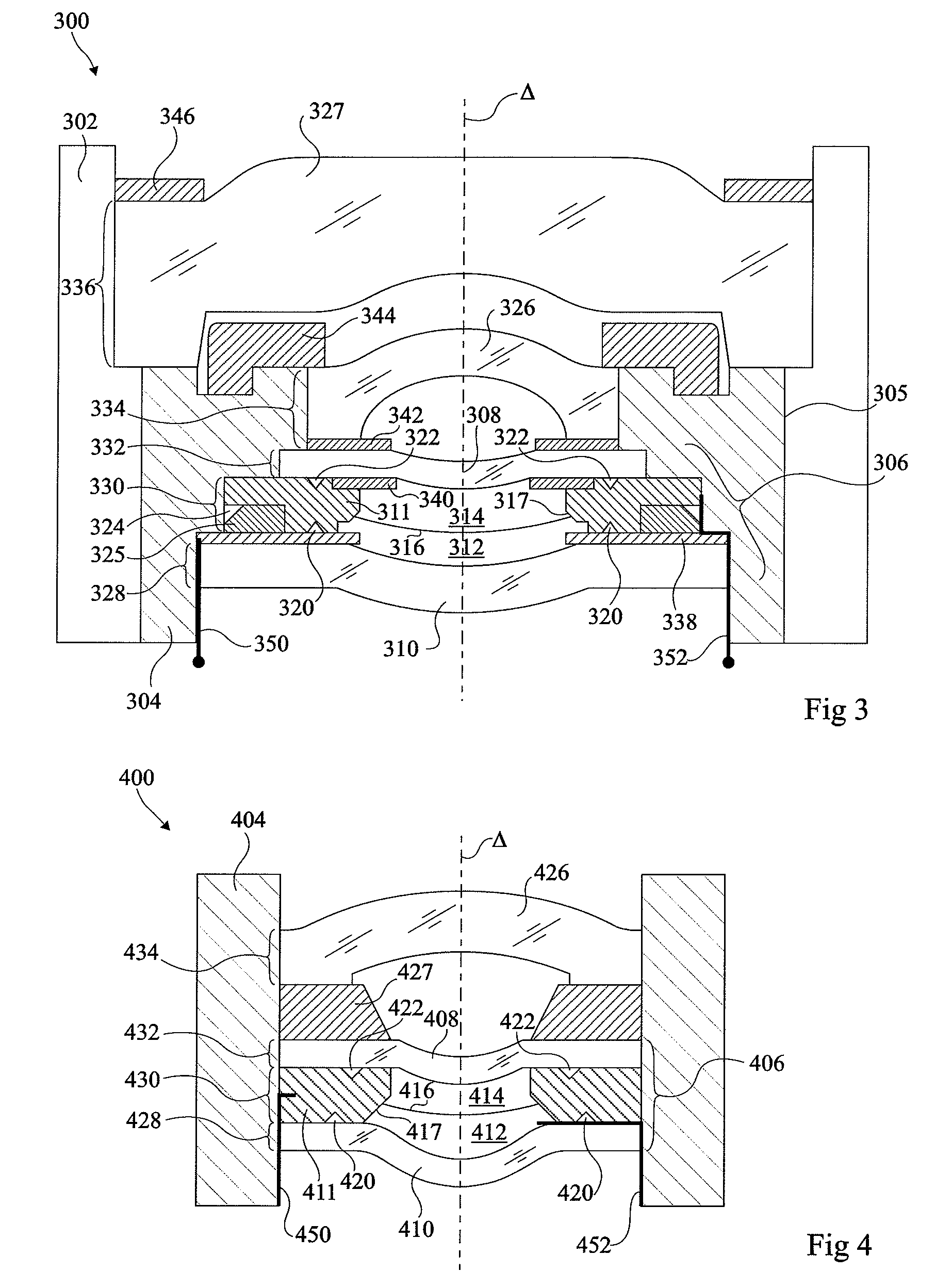
[0032]FIG. 3 illustrates an optical lens arrangement 300 comprising an outer lens barrel 302 and an inner lens barrel 304 supporting a liquid lens 306 and a number of fixed lenses. The inner and outer lens barrels 302, 304 for example meet each other at a cylindrical or slightly conical interface 305, allowing the position of the inner and outer lens barrels to be adjusted with respect to each other.

[0033]The inner lens barrel 304 houses liquid lens 306 which comprises fixed lenses 308 and 310. An annular body 311 is sandwiched between these fixed lenses, defining a chamber containing a conducting liquid 312 and an insulating liquid 314, which meet at a liquid interface 316. Fixed lenses 308, 310 for example comprise hydrophilic and insulating coatings respectively deposited on their inner surfaces, where these lenses contact the liquids 314 and 312. Interface 316 for example contacts the annular body 311 on a bevelled contact surface 317, shaped like a slice of a cone, which serves...


PUM


Abstract

An optical lens arrangement including a lens barrel having a monolithic structure and including a first, a second, a third, and a fourth contact region having a common axis, a liquid lens having a structure containing a first conductive liquid and a second insulating liquid, both liquids immiscible, having different refractive indices and meeting each other at a liquid-liquid interface the curvature of which is controllable by a voltage applied to first and second electrode, wherein the structure has first and second fixed lenses in contact respectively with one of the liquids, and a third fixed lens, wherein outer edges of the first, second and third fixed lenses are positioned in contact with respective first, second and third contact regions of the lens barrel to align the first, second and third fixed lenses with each other, and wherein the fourth contact region contacts an edge of the liquid-liquid interface.

Description

FIELD OF THE INVENTION[0001]The present invention relates to an optical lens arrangement for a number of fixed lenses and a liquid lens, and in particular to an optical lens arrangement comprising a lens barrel.BACKGROUND OF THE INVENTION[0002]A number of embodiments of variable focus liquid lenses are described in European patent No 1166157. FIG. 1 of the present application corresponds to FIG. 12 of that patent and illustrates an example of a variable focus liquid lens according to the prior art.[0003]As shown in FIG. 1, the variable focus lens comprises a fluid chamber with two insulating transparent plates 100 and 102 and an optical axis Δ. Plate 102 comprises a conical or cylindrical recess, with a side face 104 inclined with respect to the optical axis Δ of the device, and which receives a drop of a first liquid which is an insulating liquid 106. The remainder of the chamber extending up to transparent plate 100 is filled with a second liquid 108, which is a conducting liquid....

Claims


Application Information

Patent Timeline
IPC IPC(8): G02B3/14
CPCG02B3/14
Inventor CRAEN, PIERREBOULIN, YVES-SEBASTIEN
Owner VARIOPTIC SA
Why Eureka
Try Eureka