
System and method for image reconstruction

Inactive Publication Date: 2005-12-29
GENERAL ELECTRIC CO
View PDF25 Cites 32 Cited by
  • Summary
  • Abstract
  • Description
  • Claims
  • Application Information

AI Technical Summary

Benefits of technology

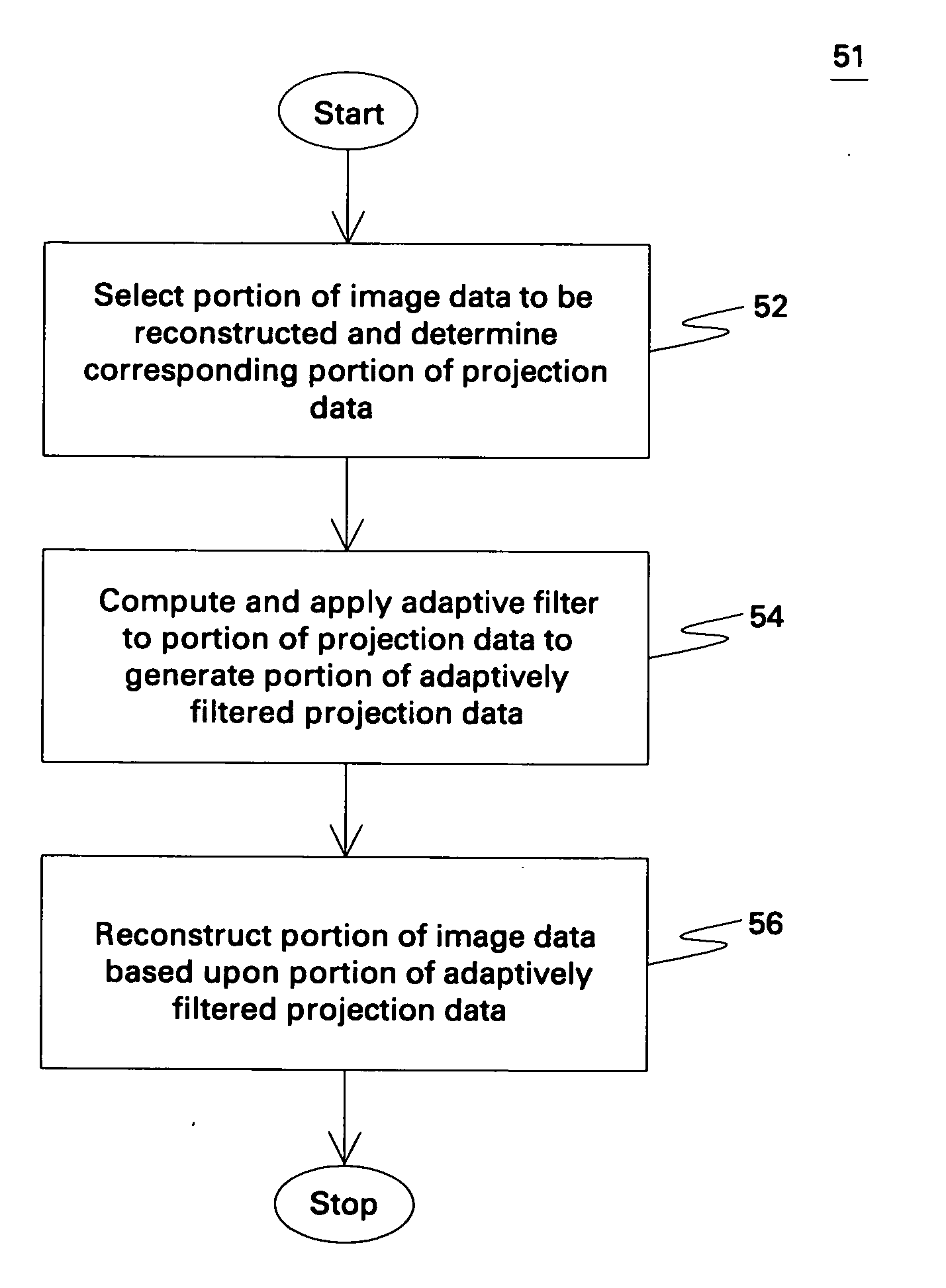
[0006] Embodiments of the present techniques address this and other needs. In one embodiment, a method for reconstructing image data acquired by a computed tomography system is provided. The method comprises selecting a portion of image data to be reconstructed and determining the corresponding portion of projection data. An adaptive fi

Problems solved by technology

However, existing adaptive filtering techniques are independent of the pixel (or a group of pixels) being reconstructed.

Method used


Image

  • System and method for image reconstruction
  • System and method for image reconstruction
  • System and method for image reconstruction

Examples


Embodiment Construction

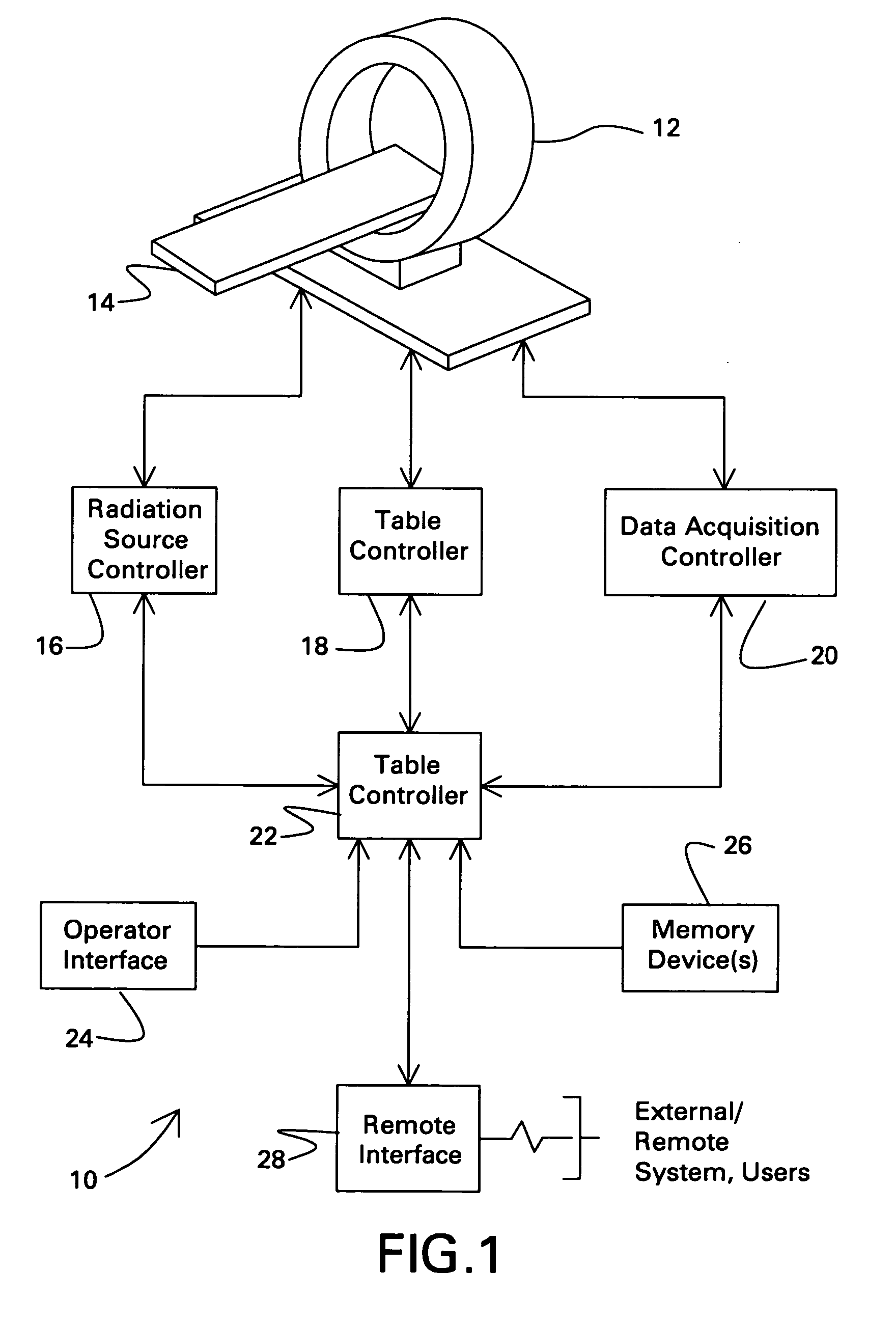
[0013] Turning now to the drawings, referring first to FIG. 1, a computed tomography (CT) system is illustrated and designated generally by reference numeral 10. In the illustrated embodiment, the computed tomography (CT) system 10 is designed to acquire, process and reconstruct image data in accordance with the present technique as will be described in greater detail below. The CT system 10 comprises a scanner 12 formed of a support structure and internally containing one or more stationary or rotational, distributed sources of X-ray radiation (not shown in FIG. 1) and one or more stationary or rotational digital detectors (not shown in FIG. 1). The scanner is configured to receive a table 14 or other support for a patient, or, more generally, a subject to be scanned. The table can be moved through an aperture in the scanner to appropriately position the subject in an imaging volume or scanning plane during imaging sequences.

[0014] The system further includes a radiation source co...


PUM


Abstract

A method for reconstructing image data acquired by a computed tomography system is provided. The method comprises selecting a portion of image data to be reconstructed and determining a corresponding portion of projection data. An adaptive filter is computed and applied to the portion of projection data to generate a portion of adaptively-filtered projection data. The adaptive filter is computed based upon desired quality properties of the portion of image data. Finally, the portion of image data is reconstructed based upon the portion of adaptively-filtered projection data. The step of selecting, computing and reconstructing is repeated for every pixel or group of pixels comprising the image data.

Description

BACKGROUND OF THE INVENTION [0001] The present invention relates generally to the field of imaging systems. In particular, the invention relates to a system and method for reconstructing image data acquired from a computed tomography imaging system. [0002] Computed Tomography (CT) scanners operate by projecting fan shaped or cone shaped X-ray beams through an object. The X-ray beams are generated by an X-ray source, and are generally collimated prior to passing through the object being scanned. The attenuated beams are then detected by a set of detector elements. Each detector element produces a signal based on the intensity of the attenuated X-ray beams, and these signals are processed to produce projection data, also called sinogram data. By using reconstruction techniques, such as filtered backprojection, useful images are formed from the projection data. [0003] A computer is able to process and reconstruct images of the portions of the object responsible for the radiation attenu...

Claims


Application Information

Patent Timeline
IPC IPC(8): G06K9/00G06K9/40
CPCG06T11/005G06T2211/421G06T2211/416Y10S378/901
Inventor DE MAN, BRUNO KRISTIAAN BERNARDEDIC, PETER MICHAELBASU, SAMIT KUMAR
Owner GENERAL ELECTRIC CO
Learn More