
Method and system for adjusting the image acquisition size in a biplane angiography

Active Publication Date: 2009-07-30
SIEMENS HEATHCARE GMBH
View PDF3 Cites 2 Cited by
  • Summary
  • Abstract
  • Description
  • Claims
  • Application Information

AI Technical Summary

Problems solved by technology

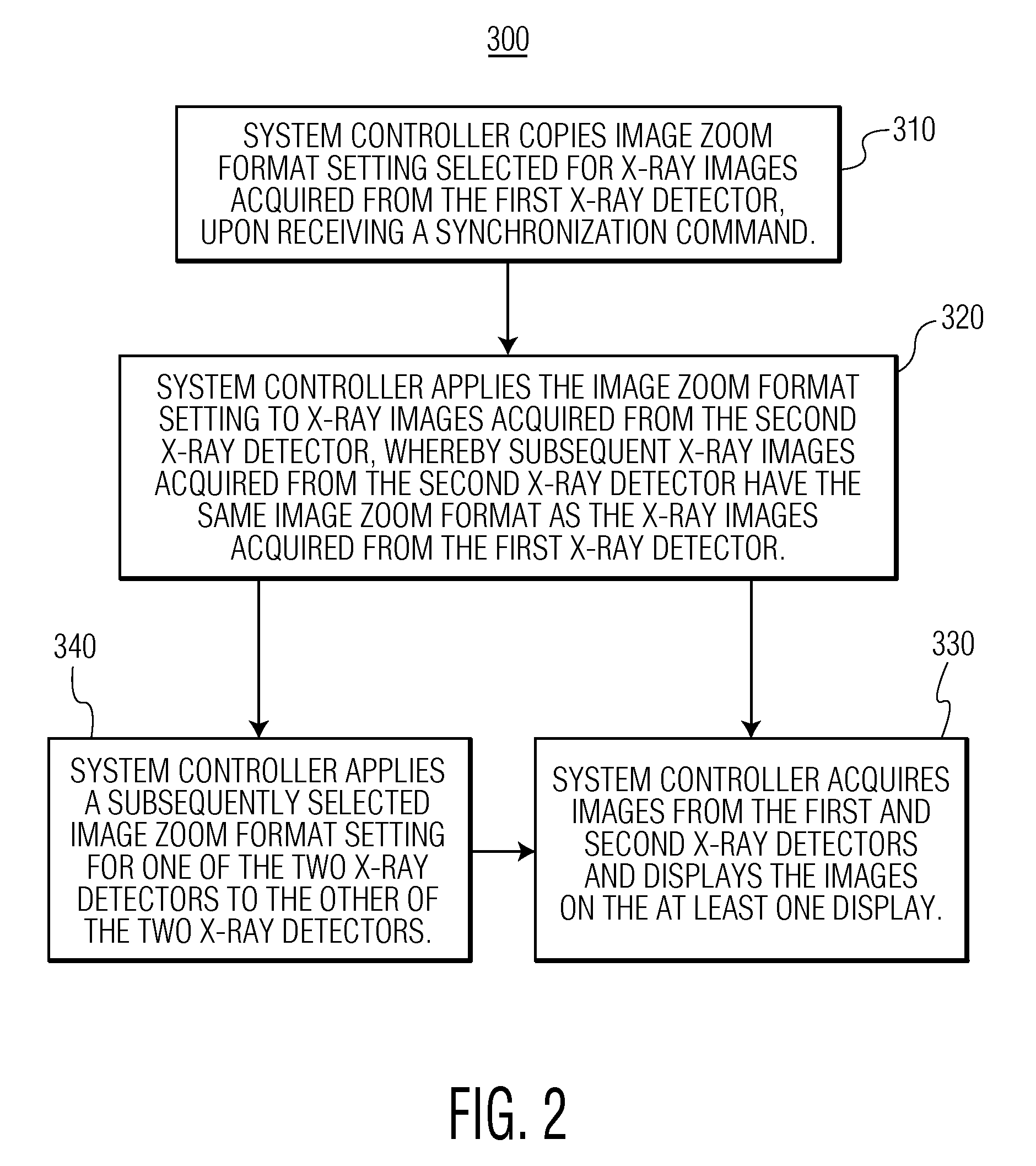
This, however, requires the user to adjust the image zoom formats twice, one for each of the two x-ray detectors, and results in duplication of tasks that add undesirable time to medical procedures requiring biplane angiography.

Method used


Image

  • Method and system for adjusting the image acquisition size in a biplane angiography
  • Method and system for adjusting the image acquisition size in a biplane angiography
  • Method and system for adjusting the image acquisition size in a biplane angiography

Examples


Embodiment Construction

[0011]An “image zoom format” refers to one of a number of image sizes that an x-ray image being acquired from the x-ray detectors of a biplane angiography system can be formatted to. An “image zoom format setting” refers to a particular image zoom format selected from a set of a number of image zoom formats. “X-ray plane image” is an x-ray image acquired from an x-ray detector corresponding to one of the two imaging planes in a biplane angiography system.

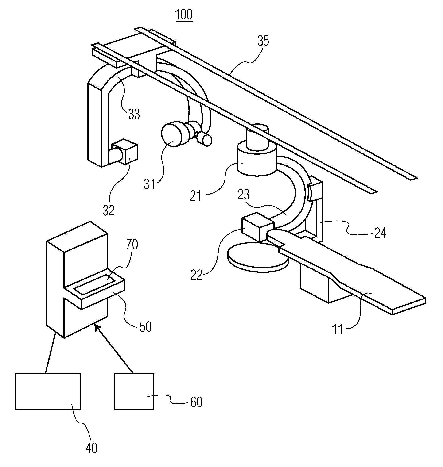
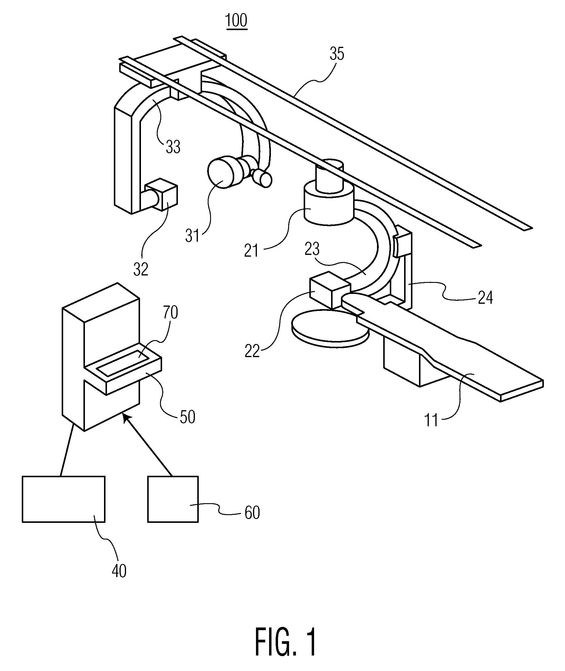
[0012]Referring to FIG. 1, an exemplary biplane angiography system 100 is shown. The biplane angiography system 100 may comprise a first pair of an x-ray source 22 and an x-ray detector 21, a second pair of an x-ray source 32 and an x-ray detector 31, at least one display 40 and a system controller 50. The system controller 50 is connected to and in communication with the first pair of x-ray source 22 and x-ray detector 21, the second pair of x-ray source 32 and x-ray detector 31 and the at least one display 40. The first pair of x-...


PUM


Abstract

A system and method are disclosed for acquiring images in a biplane angiography system. The system and method allows synchronization of the image zoom format settings for the x-ray images acquired from the two planes of the biplane angiography system thus allowing the user to adjust the image zoom format setting for only one image plane.

Description

CROSS-REFERENCE TO RELATED APPLICATIONS[0001]This is a non-provisional application of pending U.S. provisional patent application Ser. No. 61 / 024,329, filed Jan. 29, 2008, the entirety of which application is incorporated by reference herein.FIELD OF THE DISCLOSURE[0002]The disclosure is related to methods for acquisition of biplane angiography images.BACKGROUND[0003]An angiogram is a specialized x-ray examination of the blood vessels of the brain and other parts of the body. Angiography involves an injection of contrast medium to outline the blood vessels in order to render them visible in the x-ray images. The injection of the contrast medium is typically done through a small tube inserted into the groin of the patient.[0004]Biplane angiography system features two sets of x-ray tube / x-ray detector pairs positioned at 90-degree angles allowing the blood vessels to be viewed from two different angles at the same time. Compared to the old single plane imaging equipment which gave a v...

Claims


Application Information

Patent Timeline
IPC IPC(8): H05G1/64
CPCA61B6/02A61B6/504A61B6/481A61B6/4441
Inventor KARGAR, SOROOSHLEI, WENG
Owner SIEMENS HEATHCARE GMBH
Learn More