

Customer behavior monitoring system, method, and program
a behavior monitoring and customer technology, applied in the field of customer behavior monitoring system, method and program, can solve the problems of not disclosing reasons, and the uncertainty that the flow line data correlated with purchase information is the actual data relating,
- Summary
- Abstract
- Description
- Claims
- Application Information
AI Technical Summary
Benefits of technology
Problems solved by technology
Method used
Image

Examples
embodiment 1
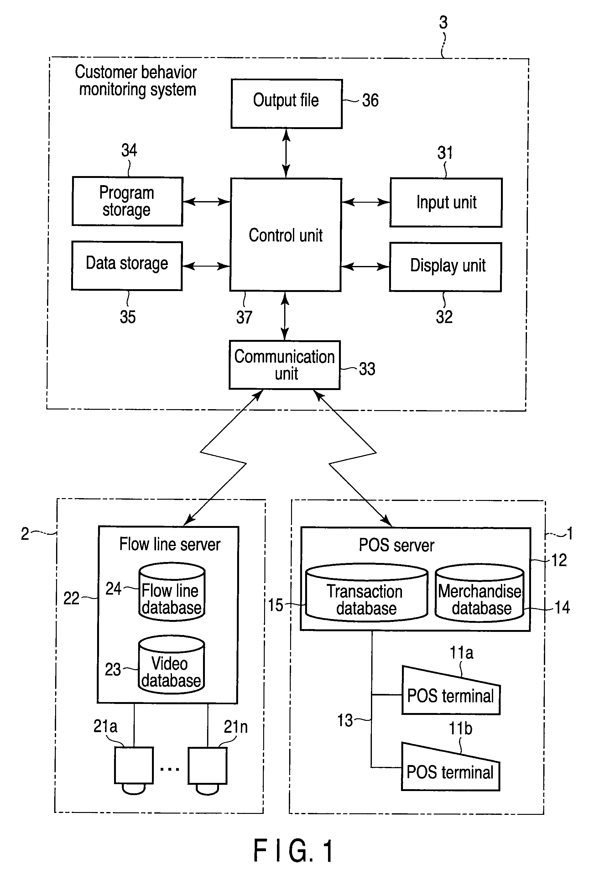
[0037]This embodiment comprises a sales management system 1, a flow line data management system 2, and a customer behavior monitoring system 3, as shown in FIG. 1.
[0038]The sales management system 1 includes a plurality of POS terminals 11a and 11b and a single POS server 12. The POS terminals 11a and 11b are installed in appropriate locations in a store. The POS server 12 functions as a host to the POS terminals 11a and 11b. The POS server 12 connects the POS terminals 11a and 11b through a communication circuit 12 such as a local area network (LAN). The sales management system 1 configured as above is generally called a POS system.
[0039]The POS terminals 11a and 11b function as transaction payment terminals. Namely, when data on merchandise purchased by a customer is input, the POS terminals 11a or 11b enters sales data on the merchandise. When data on the money paid by the customer is input, the POS terminal issues a receipt, and settle the transaction with the customer.
[0040]Eac...
embodiment 2
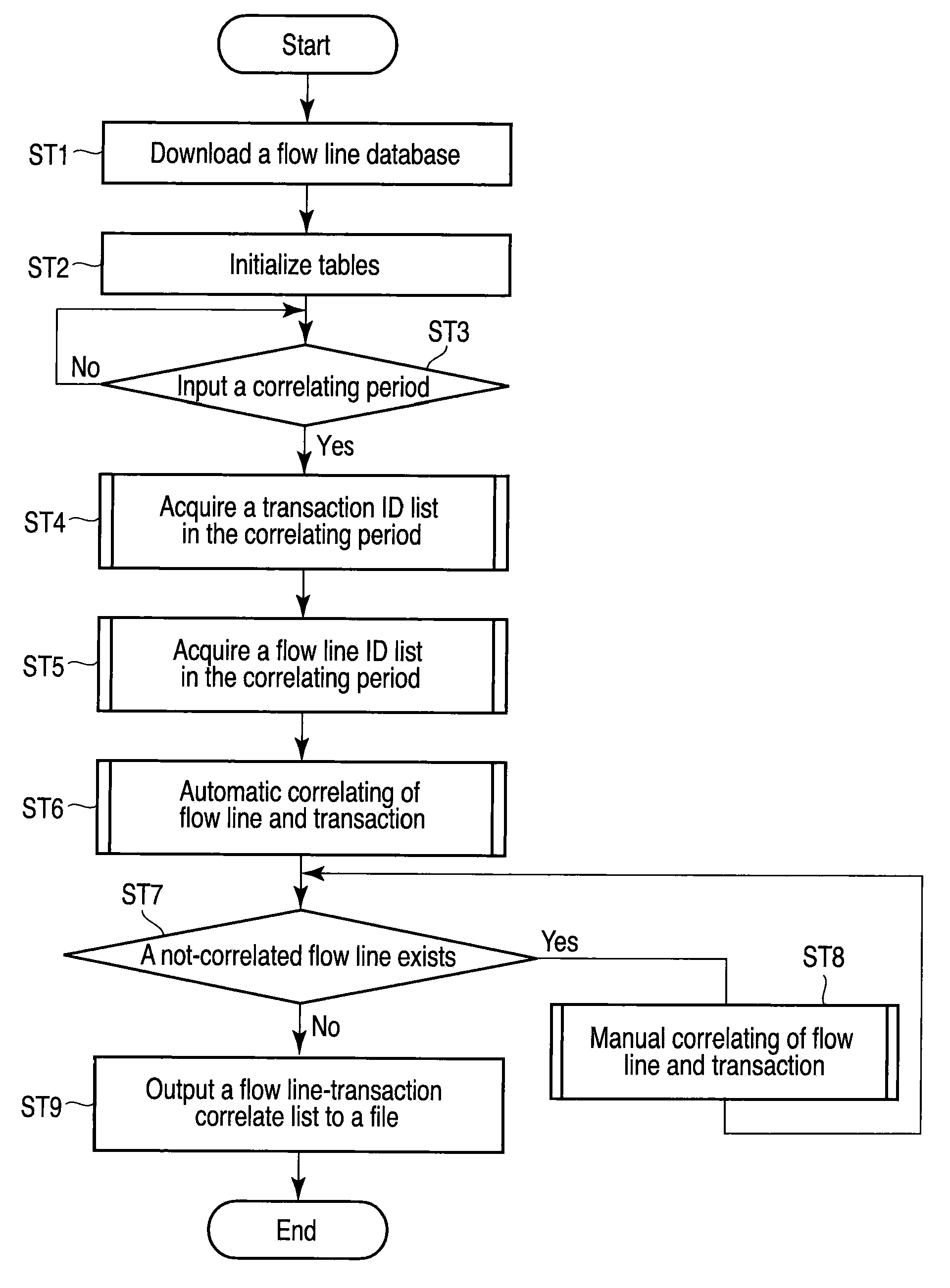
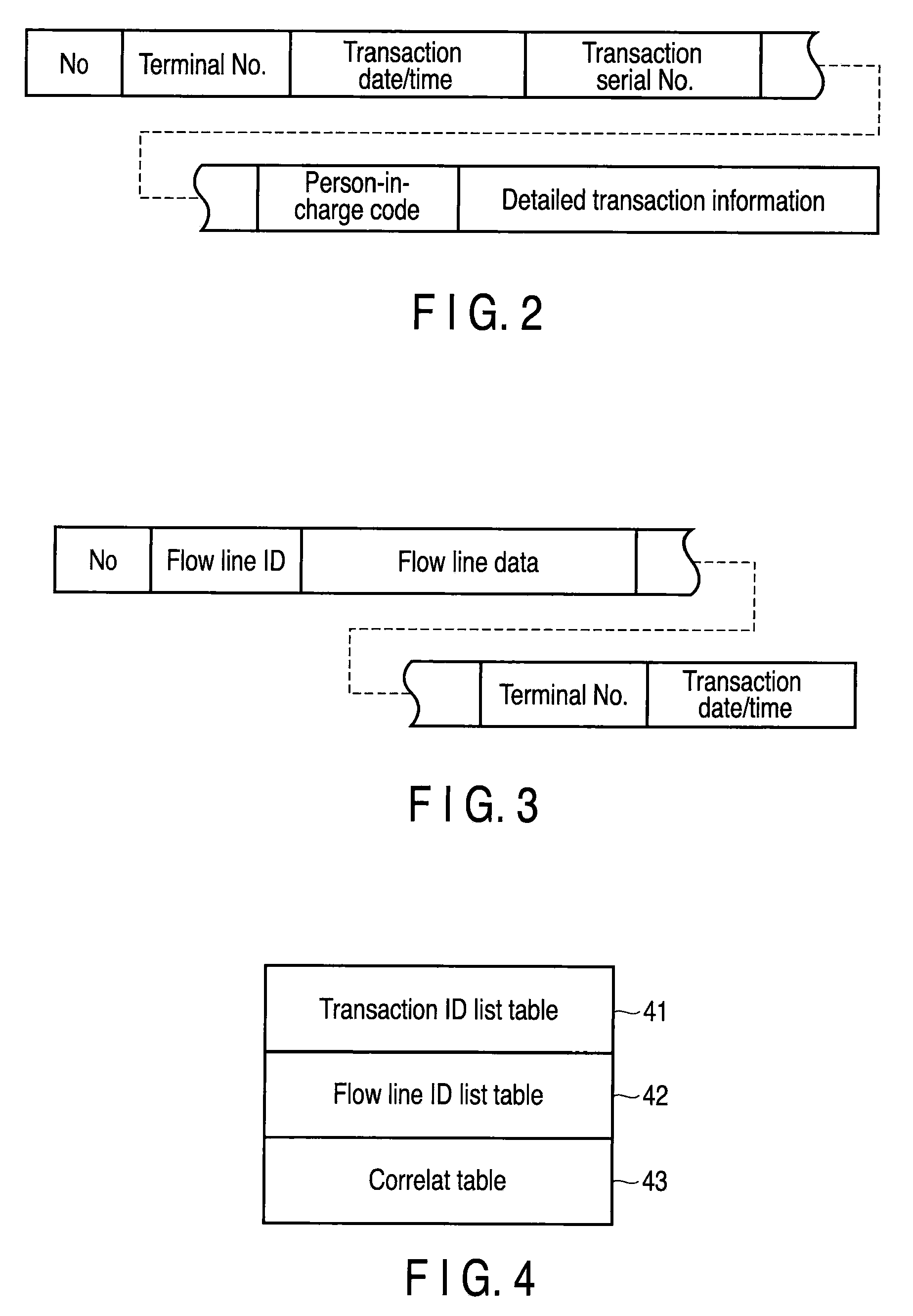
[0125]In the first embodiment, each flow line in a flow line ID list and each transaction ID (a terminal number, transaction date and time, and a transaction serial number) in a transaction ID list are combined, so that a difference between the transaction dates and time is minimum. Here, the transaction date and time data added to a flow line ID is the date and time counted by a clock IC built into the flow line server 22. In contrast, the transaction date and time data included in a transaction ID is the date and time counted by a clock IC built into each of the POS terminals 11a and 11b. Thus, even if the time is periodically adjusted, a time difference may occur.
[0126]When a time difference occurs, even if a combination in which the difference between the transaction dates and time is minimum, the combination may not be correct. Thus, in the second embodiment, correlating is made while correcting a time difference.
[0127]The flowchart of FIG. 14 shows steps of a main process exec...
embodiment 3
[0139]A terminal number added to each flow line data in the flow line database 24 is determined and input by the operator on the screen of the display unit 32. Thus, a wrong terminal number may be added by mistake in judgment or input.
[0140]In the first and second embodiments, correlating is based on a condition that a terminal number added to each flow line ID coincides with a terminal number of a transaction ID. Thus, when a wrong terminal number is added, correct correlating is impossible. Such a defect is prevented in a third embodiment.
[0141]In the third embodiment, a terminal number table 44 is formed in the data storage 35. In the terminal number table 44, terminal numbers of POS terminals 11aand 11b are set in ascending order from 1 corresponding to correspondence table numbers, as shown in FIG. 16.
[0142]In the third embodiment, when the number of repetitions k exceeds a maximum value kMAX in the manual correlating process in step ST75 shown in FIG. 10, the control unit 37 e...
PUM
 Abstract
Description
Claims
Application Information