
Self-supporting manual toothbrush

a self-supporting, toothbrush technology, applied in the field of dental care, can solve the problems of large size, inability to insert through the aperture, and large size of the handle, and achieve the effect of reducing the comfort of cleaning, and reducing the difficulty of cleaning

Inactive Publication Date: 2009-08-06
VORSTEN ENTERPRISES
View PDF10 Cites 9 Cited by
  • Summary
  • Abstract
  • Description
  • Claims
  • Application Information

AI Technical Summary

Benefits of technology

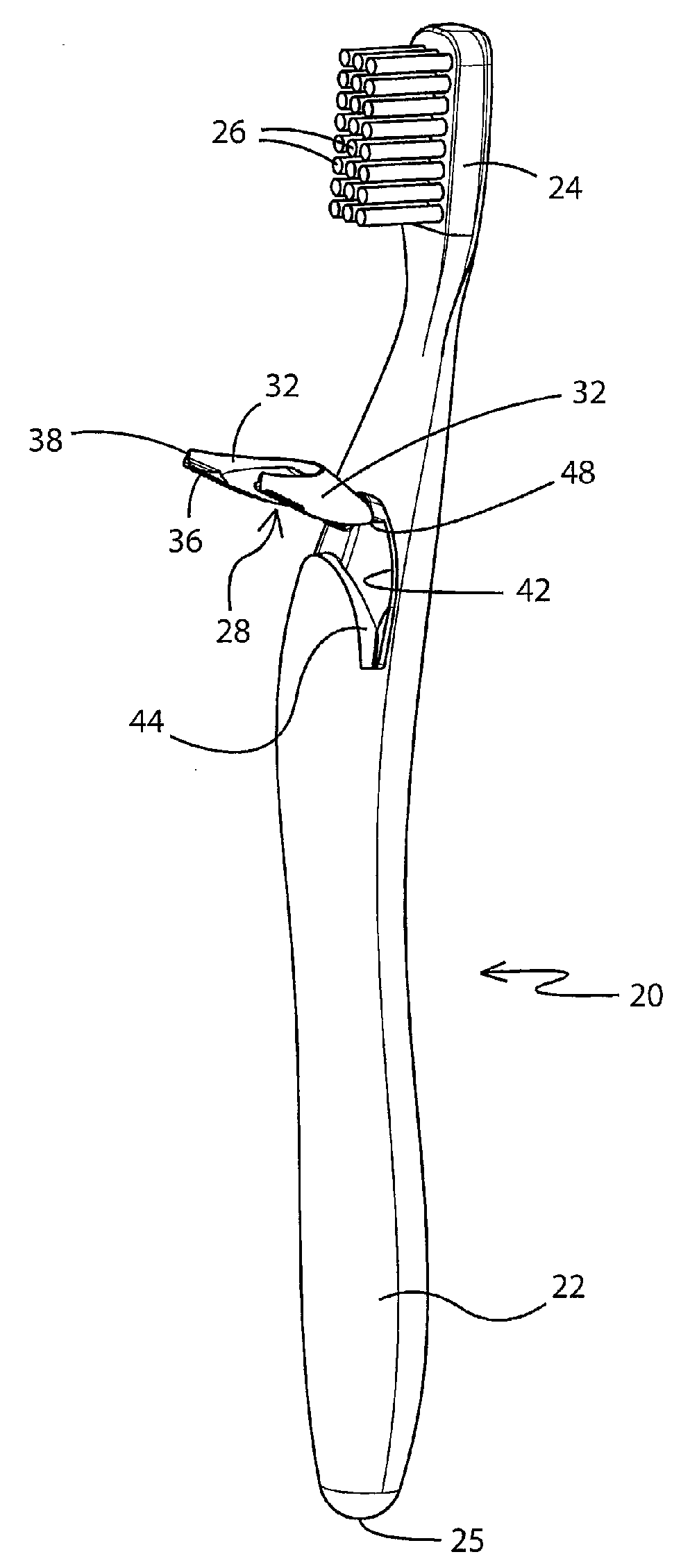
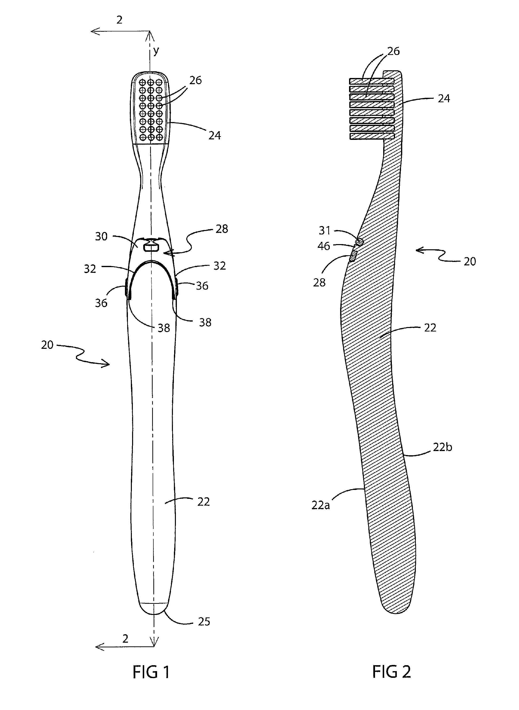
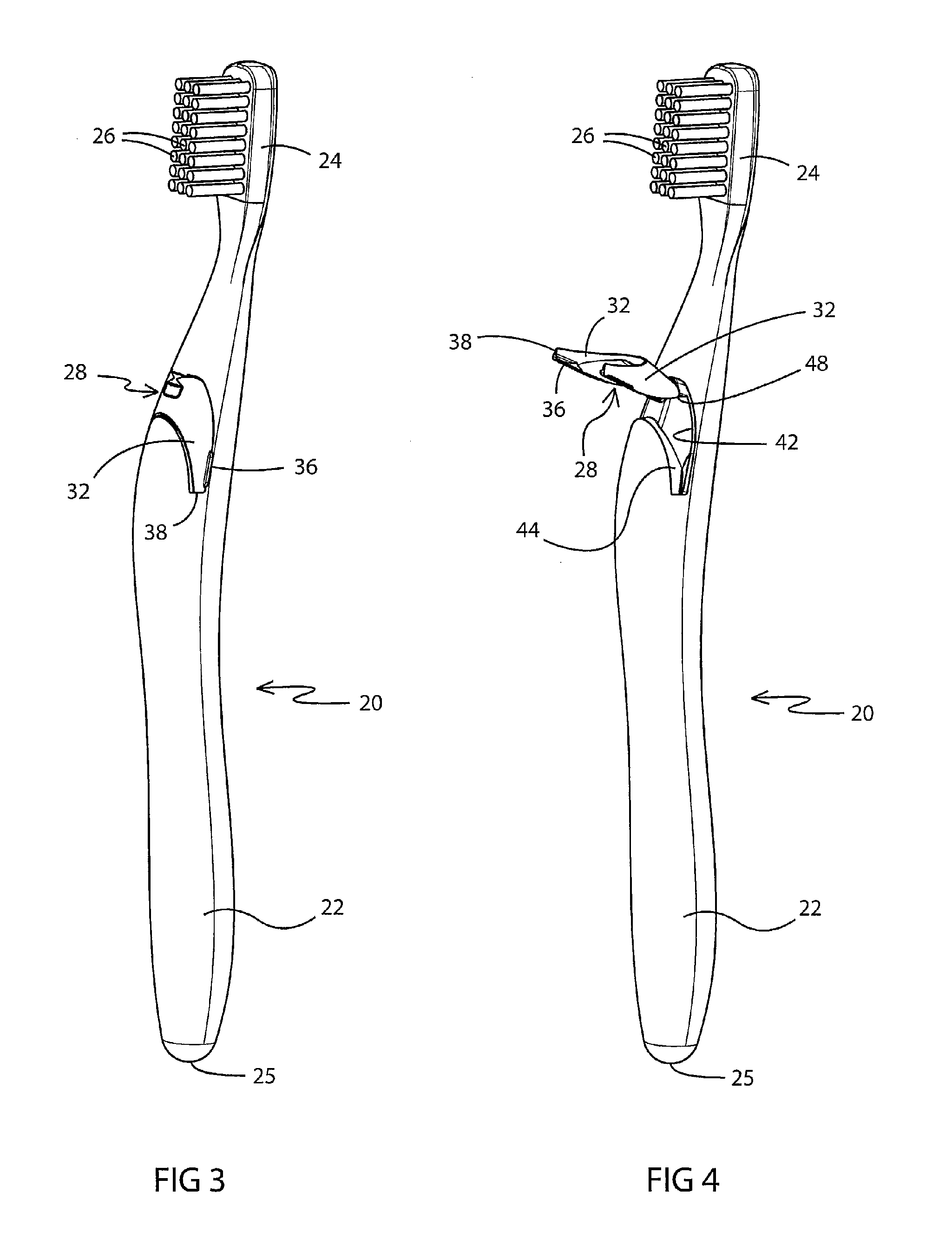
"The present invention is a toothbrush with a pivotable stand that can be moved between a collapsed and extended position. The stand is designed to be placed in contact with a horizontal surface to orient the brush in a head-down position with the bristles above the surface to drip-dry. The stand is positioned on the handle so that no portion of it enters the user's mouth. The technical effect of this invention is to provide a toothbrush that can be easily oriented for effective cleaning while maintaining the bristles at a safe distance from the surface being cleaned."

Problems solved by technology

The design of present-day toothbrushes, however, has rendered these fixtures essentially useless because of the changes in handle design and materials.
These changes have resulted in larger, rubber grip handles that cannot be inserted through the apertures in the toothbrush fixtures.
Additionally, many people are no longer comfortable with putting their brushes in close proximity to those of other people, even members of their own family, as it is now commonly known that infections can be easily passed from one family member's oral care products to another.
People are also not comfortable resting their toothbrushes on bathroom countertops and then placing them into their mouth.
Once again, however, people are not comfortable placing their toothbrush with others in such glasses.
When brushes are stood upright, the water and foreign materials tend to drip from one region of bristles to another.
Traveling is also an issue as hotels do not make provision for a suitable place for resting one's toothbrush.
The counter is an especially unsuitable place for resting the brush and the types of plastic cups that are provided in hotels are lightweight and will tend to fall over if a brush is placed in it.
Firstly, it stops the water, toothpaste and removed material from sliding down the handle and onto the user's hand.
Secondly, it was designed to support the bristle portion of the brush so when the brush is laid down, the bristle portion will be aired.
Furthermore, the guard is an obstruction on the handle and would likely make the brush sufficiently difficult to hold that the user will remove the same.
Again, however, the guard is an obstruction on the handle.
This guard is sufficiently large enough that it might also be a problem for the user during actual brushing of the teeth as the guard extends away from the brush handle to such a degree that it might strike the user's chin or cheek.
One of the problems with this design is that the fluted paths will tend to act as guides for slurry to flow down toward the user's hand.
This design is also problematic from a hygenic point of view.
Obviously, the user will run the brush, including the handle, under the tap to remove this mixture of toothpaste and removed materials, but this will cause water to flow into the cover.

Method used


Image

  • Self-supporting manual toothbrush
  • Self-supporting manual toothbrush
  • Self-supporting manual toothbrush

Examples


second embodiment

[0044]In accordance with a specific feature of the second embodiment, stand 130 further includes a longitudinally aligned lever 154 that extends outwardly away from rod 131 and in the opposite direction to legs 132. When stand 128 is secured to handle 122, lever 154 is introduced into recess 142 and into cavity 152. Proximate rear wall 122b of handle 122, cavity narrows to forms slot 150. Lever 154 is sized so that at least the terminal end 154a thereof is received in slot 150. When stand 128 is in the collapsed position (FIGS. 10, 11&15), legs 132 of stand 128 extend downwardly toward bottom end 125 of handle 122 and terminal end 154a of lever 154 extends upwardly toward head 124 of brush 120. Terminal end 154a abuts end 150a of slot 150. When stand 128 is in this collapsed position, terminal end 154a preferably does not extend outwardly from rear wall 122b of brush 120 as is shown in FIG. 11. When stand 128 is in the extended position (FIGS. 13, 14, 16), legs 132 of stand 128 exte...

first embodiment

[0046]When stand 128 is in the extended position, toothbrush 120 can be rested on surface S by placing ends 138 of stand 128 and end 125 of brush onto surface S. As with the first embodiment, toothbrush 120 thereby is angled on surface S in a manner that head 124 and bristles 136 are kept a distance above the surface so that they may drip-dry.

[0047]It will be understood that while stand 28 is shown as having two terminal ends 38, stand 28 may alternatively be shaped so that only one terminal end will contact surface S when stand 28 is in the extended position.

[0048]It will be understood that while the stand 28 is shown pivotally mounted to the front wall 22a of handle 22, the stand may, alternatively, be mounted to a side wall or to rear wall 22b in such a location that when stand 28 is in the extended position, terminal ends 38 thereof contact surface S and retain head 24 and bristles 26 a spaced distance away therefrom. Obviously, if stand 28 is mounted to a side wall, head 24 and...


PUM


Abstract

A toothbrush with a bristled head and a handle that includes a pivotable stand. The stand is movable between a collapsed position where an interior surface of the stand is proximate an outer wall of the handle, and an extended position where the stand extends outwardly away from the outer wall and at an angle thereto. This movement is effected by contacting a small flange or a lever on the stand that extends slightly outwardly from the handle. Preferably, the stand is U-shaped and is configured to be received in a complementary cavity in the front wall of the handle. When in the extended position, the legs of the stand together with the end of the handle may be placed in contact with a horizontal surface thereby causing the brush to be oriented in a head-down position with the bristles retained a distance above the surface so that they can drip-dry.

Description

BACKGROUND OF THE INVENTION[0001]1. Technical Field[0002]This invention generally relates to dental care. More particularly, the invention relates to a toothbrush. Specifically, the invention relates to a manual toothbrush having a stand pivotally mounted to the handle and movable between a collapsed position, where it is disposed adjacent the handle, and an extended position where it angles outwardly from the handle, and when the stand is in the extended position it can be placed on a surface to hold the head and bristles of the brush off the surface.[0003]2. Background Information[0004]Both power and manual toothbrush heads need to be rinsed off after each use to dislodge debris removed from the teeth during brushing. This is typically accomplished by holding the head under running tap water. While rinsing removes most of the material trapped in the bristles, it is also necessary and recommended to allow the brush to dry as this creates a less hospitable environment for most bacte...

Claims


Application Information

Patent Timeline
Patent Type & Authority Applications(United States)
IPC IPC(8): A46B5/00A46B9/04
CPCA46B5/00A46B2200/1066A46B17/02
Inventor STEIN, VOLKERDICKIE, ROBERT G.
Owner VORSTEN ENTERPRISES
Learn More