High-pressure pneumatic apparatus

Inactive Publication Date: 2009-08-06
LIN HSIN HUNG
View PDF13 Cites 2 Cited by
  • Summary
  • Abstract
  • Description
  • Claims
  • Application Information

AI Technical Summary

Benefits of technology

[0008]The present invention is directed to an improved high-pressure pneumatic apparatus, and more particularly to a high-pressure pneumatic apparatus, which can prevent gas leakage and allow quick assembling and is safe in use. The apparatus can be used with a barrel of an a

Problems solved by technology

However, since the gas bottle is designed to be refilled with gas, gas leakage may take place insensibly and may adversely affect the shooting of the gun.
Therefore, periodical check on the gas pressure in the gas bottle and refilling the gas as needed, which are both labor-consuming

Method used


Image

  • High-pressure pneumatic apparatus
  • High-pressure pneumatic apparatus
  • High-pressure pneumatic apparatus

Examples


Example

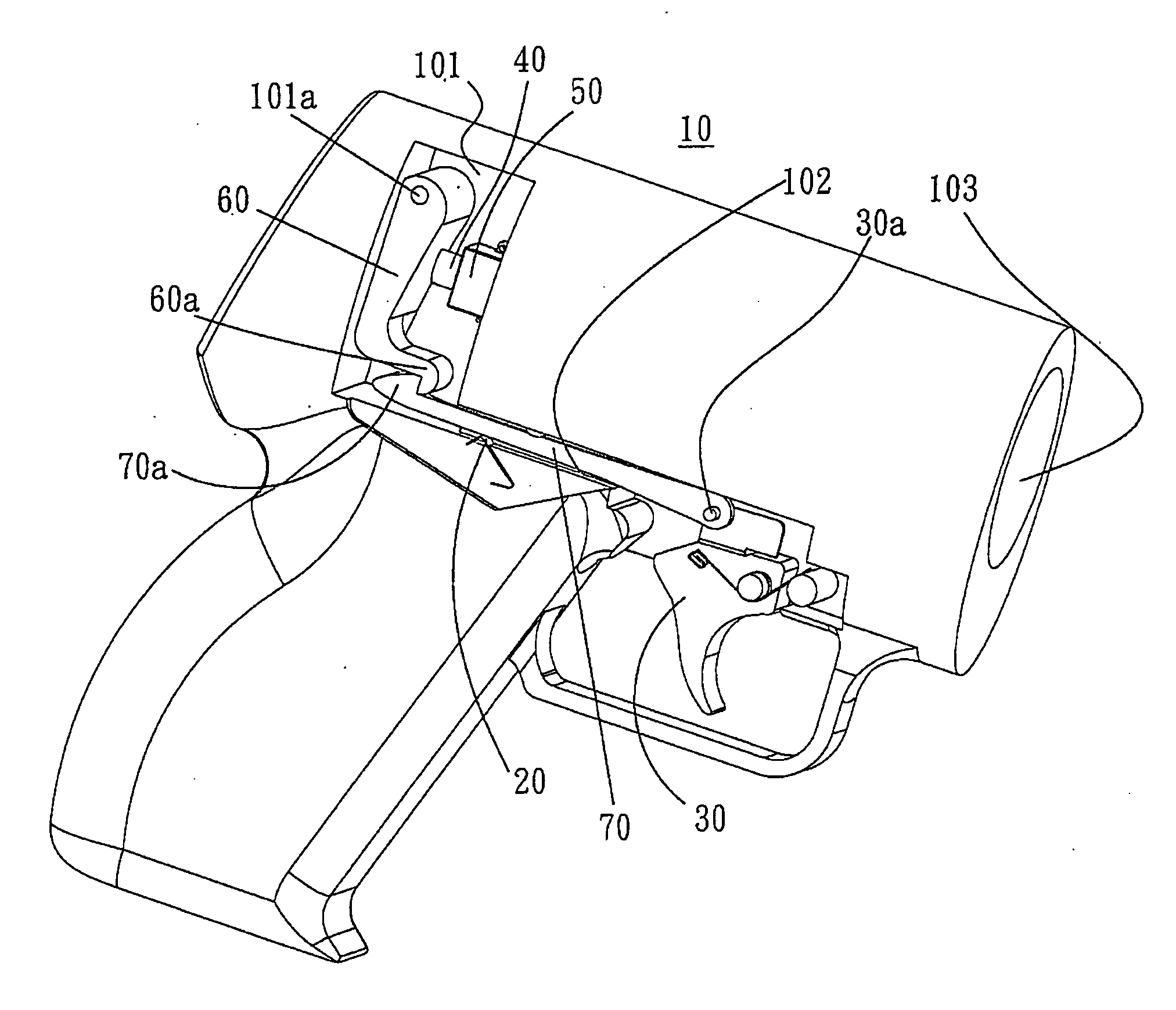
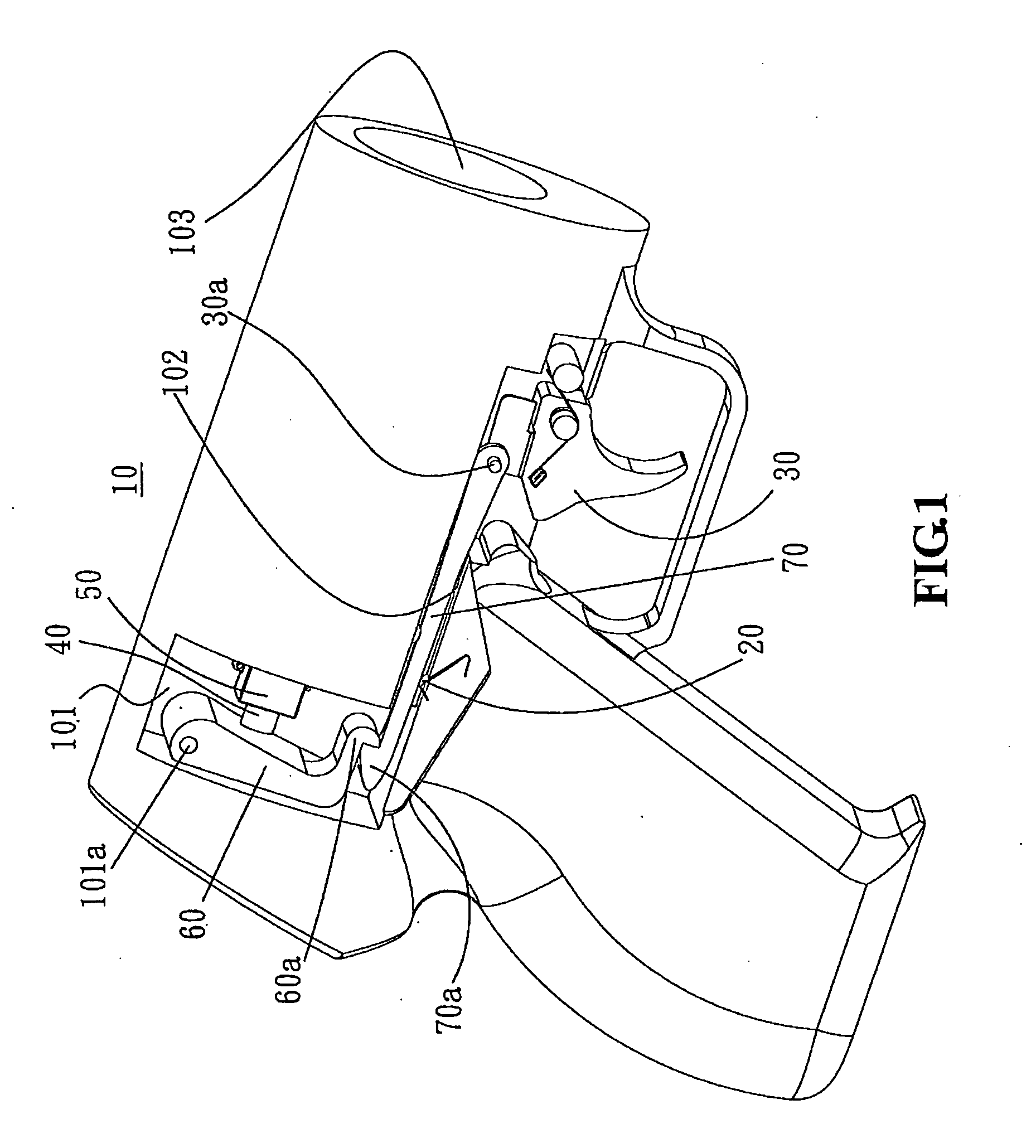
[0020]An improved high-pressure pneumatic apparatus comprises an actuation gun 10, a gas-pressure device 80, and a recessed disk 95.

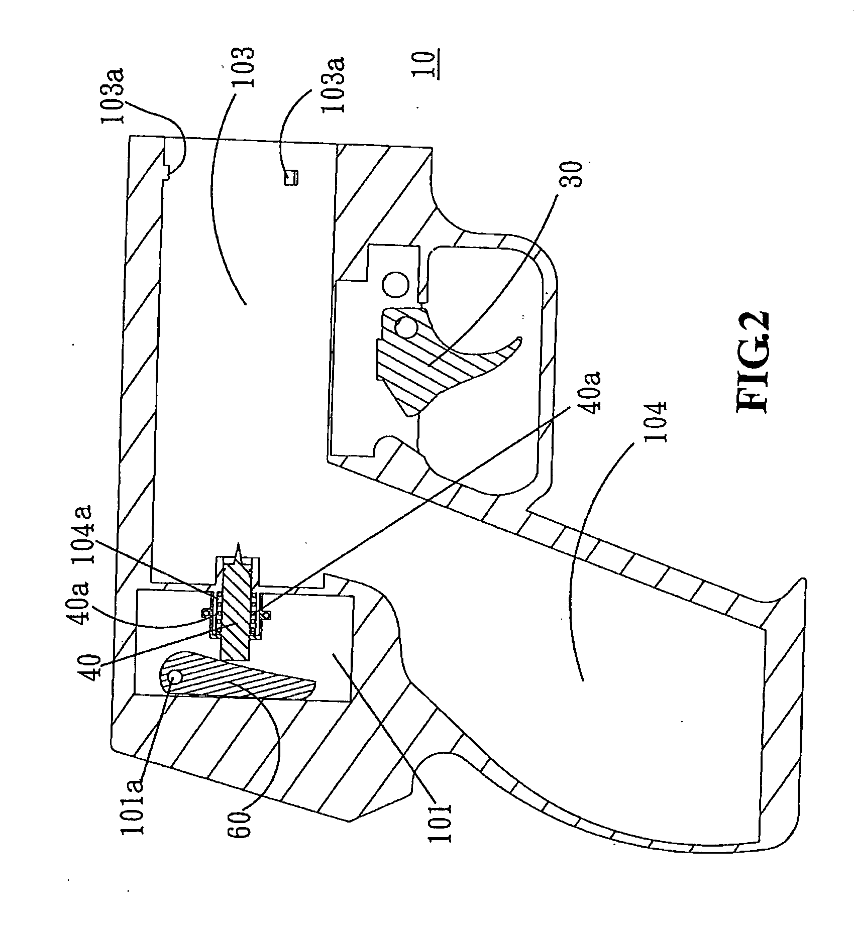
[0021]Referring to FIGS. 1 and 2, the actuation gun 10 mainly includes a recess 101 and a forwardly extended shaft slot 102 in communication with the recess 101. A tension spring 20 is inserted in a bottom of the shaft slot 102, slightly protruding out of the shaft slot 102. In addition, a trigger 30 is disposed at a distal end of the shaft slot 102. Referring to FIG. 2, the actuation gun 10 includes a barrel gas chamber 103 at a front portion thereof. The barrel gas chamber 103 is in communication with a handle internal chamber 104. A hole in communication with the recess 101 is defined at a rear of the barrel gas chamber 103. A tube protrudes from an edge of the hole to form a tube slot 104a. A strike pin 40 and a spring 40a can be inserted through the tube slot 104a, and a cover 50 having a through hole can cover the tube slot 104a. Besides, a plural...


PUM


Abstract

An improved high-pressure pneumatic apparatus can prevent gas leakage and allows quick assembling and is safe in use. The apparatus can be used with a barrel of an anti-riot or rescue tool gun, such as a catching net gun, a line-throwing gun or a riot gun, for supplying an intensive pressure for shooting in a very short time.

Description

BACKGROUND OF THE INVENTION[0001]1. Field of the Invention[0002]The present invention relates to an improved high-pressure pneumatic apparatus, and more particularly to a high-pressure pneumatic apparatus, which can prevent gas leakage and is safe in use.[0003]2. Description of Related Art[0004]In a conventional anti-riot or rescue tool gun, such as a catching net gun, a line-throwing gun or a riot gun, a gas bottle or a gunpowder cartridge is typically disposed at a distal end of a barrel thereof to supply a high-pressure power for shooting.[0005]However, since the gas bottle is designed to be refilled with gas, gas leakage may take place insensibly and may adversely affect the shooting of the gun. Therefore, periodical check on the gas pressure in the gas bottle and refilling the gas as needed, which are both labor-consuming and cost-consuming, are necessary for ensuring good operation of the gun.[0006]On the other hand, the conventional anti-riot or rescue tool gun that implement...

Claims


Application Information

Patent Timeline
IPC IPC(8): F41B11/06F41B11/62
CPCF41B11/62
Inventor LIN, HSIN-HUNG
Owner LIN HSIN HUNG
Why Eureka
Try Eureka