Solar Module with a Frame for Mounting a Solar Panel

a solar module and solar panel technology, applied in the direction of heat collector mounting/support, light and heating apparatus, collector casings, etc., can solve the problems of permanent damage to the solar panel and frame failure, and achieve the effect of increasing the mass of the solar modul

Inactive Publication Date: 2009-08-06
BP CORP NORTH AMERICA INC
View PDF5 Cites 64 Cited by
  • Summary
  • Abstract
  • Description
  • Claims
  • Application Information

AI Technical Summary

Problems solved by technology

Weather-based stresses can permanently damage the solar panel.
The load on the solar panel may cause the frame to fail as a portion of the solar panel comes out of or disengages from the frame, requiring replacement of the solar panel.

Method used


Image

  • Solar Module with a Frame for Mounting a Solar Panel
  • Solar Module with a Frame for Mounting a Solar Panel
  • Solar Module with a Frame for Mounting a Solar Panel

Examples


Embodiment Construction

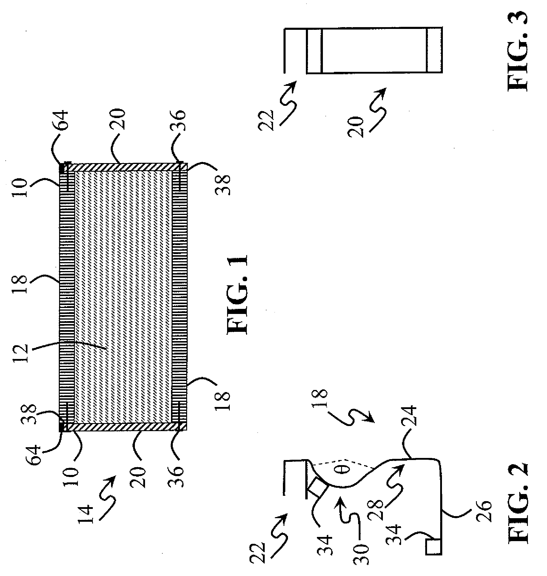
[0026]The invention, as shown in FIG. 1, is directed to solar module 14 including frame 10 for holding and / or mounting solar panel 12. Solar module 14 may include any suitable device or mechanism to convert or transform electromagnetic radiation into electricity. Electromagnetic radiation broadly includes visible light, infrared, ultraviolet and / or any other portion of the electromagnetic spectrum, such as, for example, radiation emitted from a sun and / or a star.

[0027]Electricity broadly includes direct current, alternating current, low voltage, high voltage and / or any other suitable movement of electrons for transmission, storage and / or work. Often, solar modules 14 produce direct current which may be transformed to alternating current, such as, by an inverter.

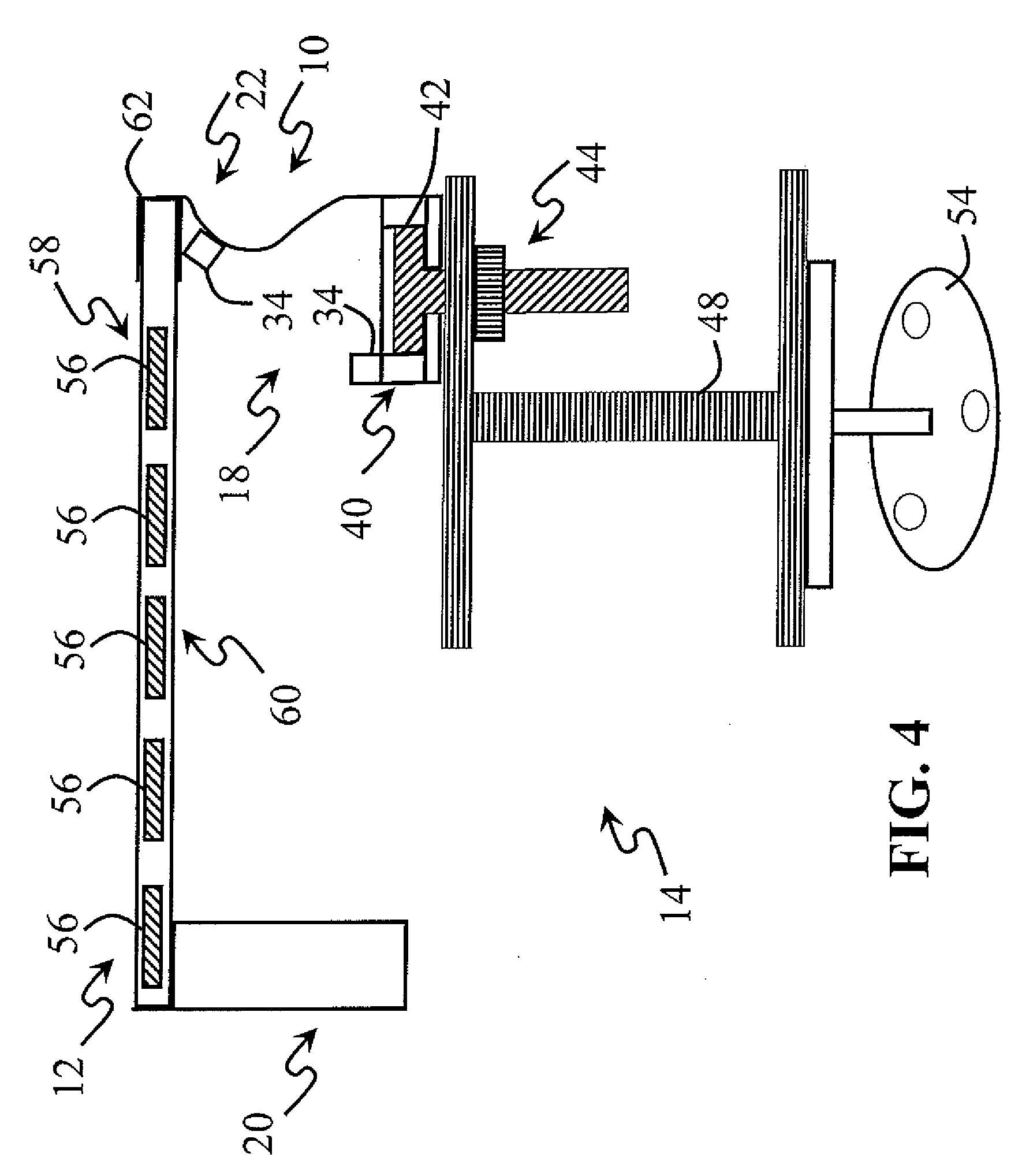
[0028]As shown in FIGS. 1 and 4 and according to certain embodiments of this invention, solar module 14 may include solar panel 12 with solar cells 56 or photodiodes, transparent sheet 58 or top cover, backing sheet 60 or bot...


PUM


Abstract

This invention relates to a frame for mounting a solar panel, where an angle frame member has a generally L-shaped cross section. The highly contoured frame member includes a riser element and a span element, where the riser element includes a straight section below an arcuate section bending towards the inside of the angle frame member. This invention also relates to solar modules, arrays of solar modules and methods of mounting solar modules, all having a highly contoured frame member.

Description

CROSS REFERENCE TO RELATED APPLICATION [0001]This patent application claims the benefit of U.S. Provisional Patent Application Ser. No. 61 / 024,992, filed on Jan. 31, 2008, and is related to U.S. design patent application titled CONTOURED SOLAR PANEL FRAME MEMBER, filed Jan. 31, 2008 (Applicant's Reference No. SL1328D). The entire content of these U.S. applications is hereby incorporated by reference.BACKGROUND OF THE INVENTION [0002]1. Field of the Invention[0003]This invention relates to solar module frames for mounting solar panels to a structure.[0004]2. Discussion of Related Art[0005]Solar technology seeks to convert energy from the sun into electricity and reduce demands on conventional sources of electricity, such as fossil fuels. The need for renewable energy sources exists in areas with temperate climates and areas with winter climates.[0006]Solar cells convert sunlight into direct current. Typically, multiple solar cells are positioned between a transparent sheet and a back...

Claims


Application Information

Patent Timeline
Patent Type & Authority Applications(United States)
IPC IPC(8): F24J2/46
CPCF24J2/464F24J2/5205F24J2/5211H01L31/048H02S20/23Y02E10/47Y02E10/50Y02B10/12H02S20/00Y02B10/20F24S25/20F24S25/33F24S80/40Y02B10/10
Inventor PLACER, NEIL V.
Owner BP CORP NORTH AMERICA INC
Why Eureka
Try Eureka