Pneumatic tire

Inactive Publication Date: 2009-08-06
YOKOHAMA RUBBER CO LTD
View PDF7 Cites 19 Cited by
  • Summary
  • Abstract
  • Description
  • Claims
  • Application Information

AI Technical Summary

Benefits of technology

[0007]According to the pneumatic tire, because each of junctions couples a protrusion onto at least one of groove walls of the circumferential main groove, rigidity of the protrusion is reinforced by the junctions. Accordingly,

Problems solved by technology

Pneumatic tires used for on-road and off-road driving have a problem such that trapping of stones (stone stuffing) in circumferential main grooves needs to be red

Method used


Image

  • Pneumatic tire
  • Pneumatic tire
  • Pneumatic tire

Examples


embodiment

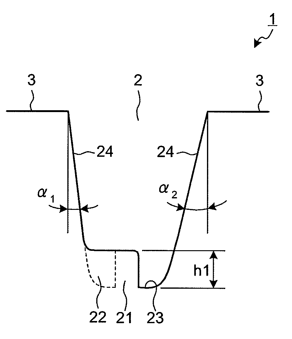
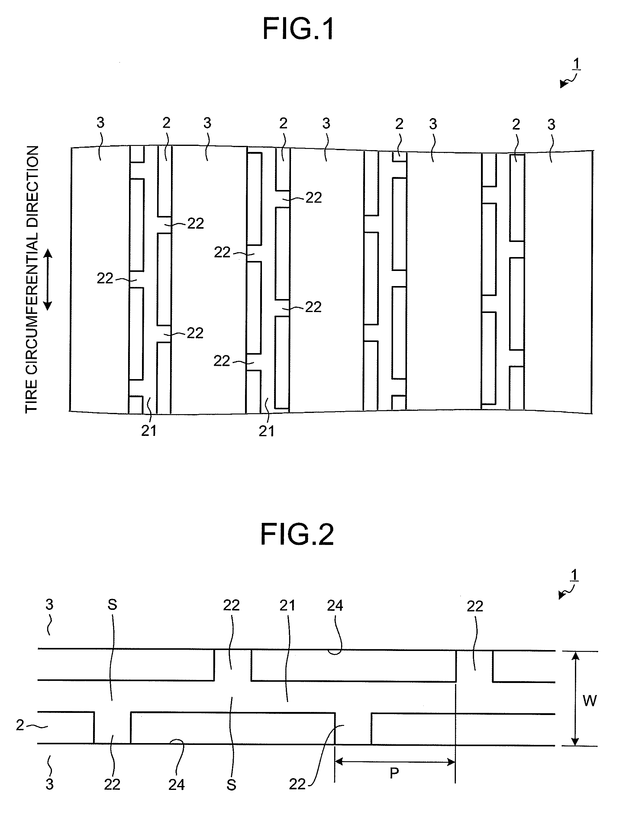
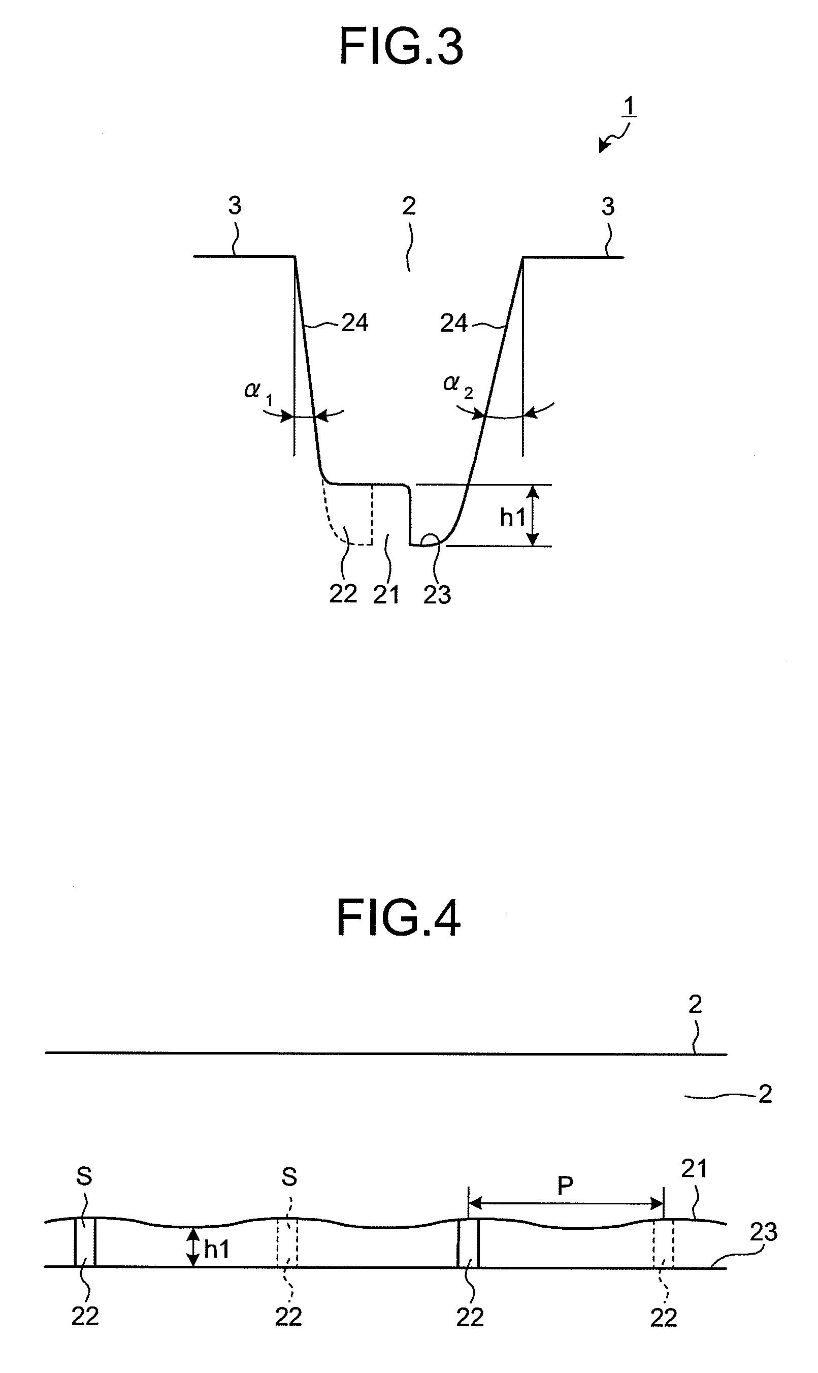
[0029]FIG. 1 is a plan view that depicts a tread surface of a pneumatic tire according to an embodiment of the present invention. FIGS. 2 and 3 are a plan view (FIG. 2) and a cross-sectional view in a tire meridian direction (FIG. 3) of a circumferential main groove of the pneumatic tire shown in FIG. 1. FIGS. 4 to 7 are schematic diagrams for explaining a configuration representing a protrusion in the circumferential main groove shown in FIG. 2 (FIGS. 4 and 5) and schematic diagrams for explaining actions of the protrusion (FIGS. 6 and 7). FIGS. 8 to 9 are schematic diagrams for explaining modifications of the pneumatic tire shown in FIG. 1. FIGS. 10 to 12 are tables in which results of performance tests of the pneumatic tires according to embodiments of the present invention are shown.

[0030]A pneumatic tire 1 includes on a tread a plurality of circumferential main grooves 2 extending in the tire circumferential direction, and a plurality of land portions 3 formed by being partitio...


PUM


Abstract

A pneumatic tire includes on a tread a plurality of circumferential main grooves extending in the tire circumferential direction, and a plurality of land portions formed by being partitioned by the circumferential main grooves. A protrusion is formed on a groove bottom of at least one of the circumferential main grooves. The protrusion continuously extends in a groove-length direction of the circumferential main groove, and a height h1 of the protrusion varies in a wavelike form along the groove-length direction. Moreover, junctions each of which couples the protrusion onto at least one of groove walls of the circumferential main groove are formed on the groove bottom of the circumferential main groove.

Description

TECHNICAL FIELD[0001]The present invention relates to a pneumatic tire. More specifically, the present invention relates to a pneumatic tire that can reduce trapping of stones in a circumferential main groove.BACKGROUND ART[0002]Pneumatic tires used for on-road and off-road driving have a problem such that trapping of stones (stone stuffing) in circumferential main grooves needs to be reduced. When such trapping of stones occurs, separation may appear on a tread by stone drilling, and a retread rate may decrease, bringing about unfavorable results. For this reason, to reduce such trapping of stones, a recent heavy duty pneumatic tire is provided with a protrusion (stone ejector) on a groove bottom of the circumferential main groove.[0003]A technology disclosed in Patent Document 1 has been known as a conventional pneumatic tire that employs such configuration. According to the conventional pneumatic tire (a pneumatic tire that includes a stone-stuffing protective protrusion), a ston...

Claims


Application Information

Patent Timeline
IPC IPC(8): B60C11/13
CPCB60C11/042B60C2011/1361Y10S152/01B60C11/047
Inventor SUZUKI, TAKAYUKI
Owner YOKOHAMA RUBBER CO LTD
Why Eureka
Try Eureka