
Image processing apparatus and image processing method

a technology of image processing and image sensing device, which is applied in the field of correction technique of the position and orientation of the image sensing device, can solve the problems of ineffective method disclosed in patent reference 3, near equal errors in the obtained calibration result, and inability to use the orientation measured value by the orientation sensor inta

Inactive Publication Date: 2009-08-06
CANON KK
View PDF8 Cites 9 Cited by
  • Summary
  • Abstract
  • Description
  • Claims
  • Application Information

AI Technical Summary

Benefits of technology

The present invention provides a technique for calculating the orientation of an orientation sensor attached to an image sensing device with respect to this image sensing device in consideration of the frequencies of possible orientations. This technique involves acquiring an image of a physical space, detecting indices in the image, calculating coordinate values for the detected indices, acquiring orientation information measured by the orientation sensor, generating sets of coordinate values and orientation information for the respective indices, calculating errors between projected positions, and calculating the orientation of the orientation sensor with respect to the image sensing device using the calculated errors and a parameter value. The technical effect of this invention is to provide a more accurate and reliable orientation sensor for image sensing devices.

Problems solved by technology

If the intrinsic parameters of the image sensing device are given, a problem of registration in MR results in that of calculating the extrinsic parameters of the image sensing device, i.e., the position and orientation of the image sensing device on a world coordinate system set on the physical space.
That is, the orientation measured value by the orientation sensor cannot be used intact as the orientation of the object to be measured on the world coordinate system, and some coordinate transform is required.
However, the method disclosed in patent reference 3 is not always effective when the orientation information at the time of use of the image sensing device that mounts the orientation sensor is taken into consideration.
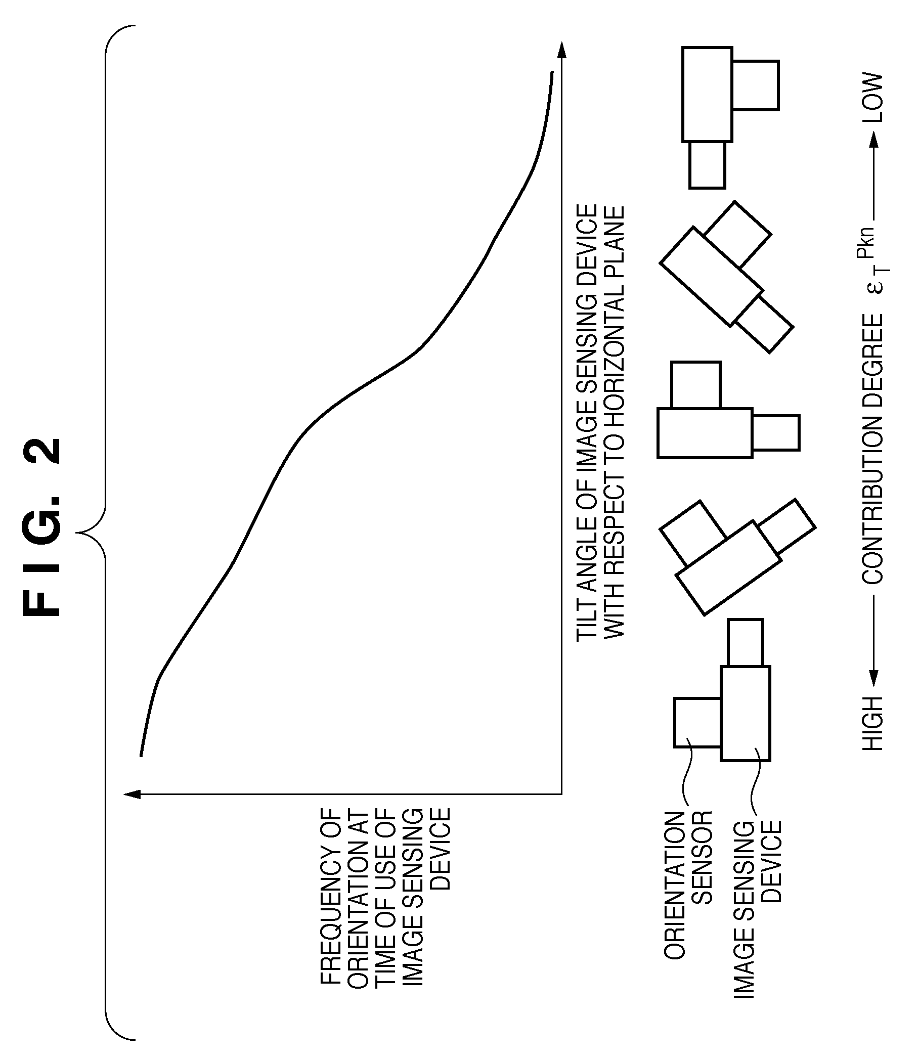
However, when the frequencies of orientations that the image sensing device takes at the time of use have differences, the obtained calibration result contains nearly equal errors independently of the orientations of the image sensing device.

Method used


Image

  • Image processing apparatus and image processing method
  • Image processing apparatus and image processing method
  • Image processing apparatus and image processing method

Examples


first embodiment

[0029]An image processing apparatus according to this embodiment acquires coordinate transform information required to transform the orientation of a sensor itself into that of an image sensing device. The image processing apparatus according to this embodiment also presents MR using a calibration result of position and orientation information of the sensor so as to confirm that calibration result. The image processing apparatus (image processing method) according to this embodiment will be described below.

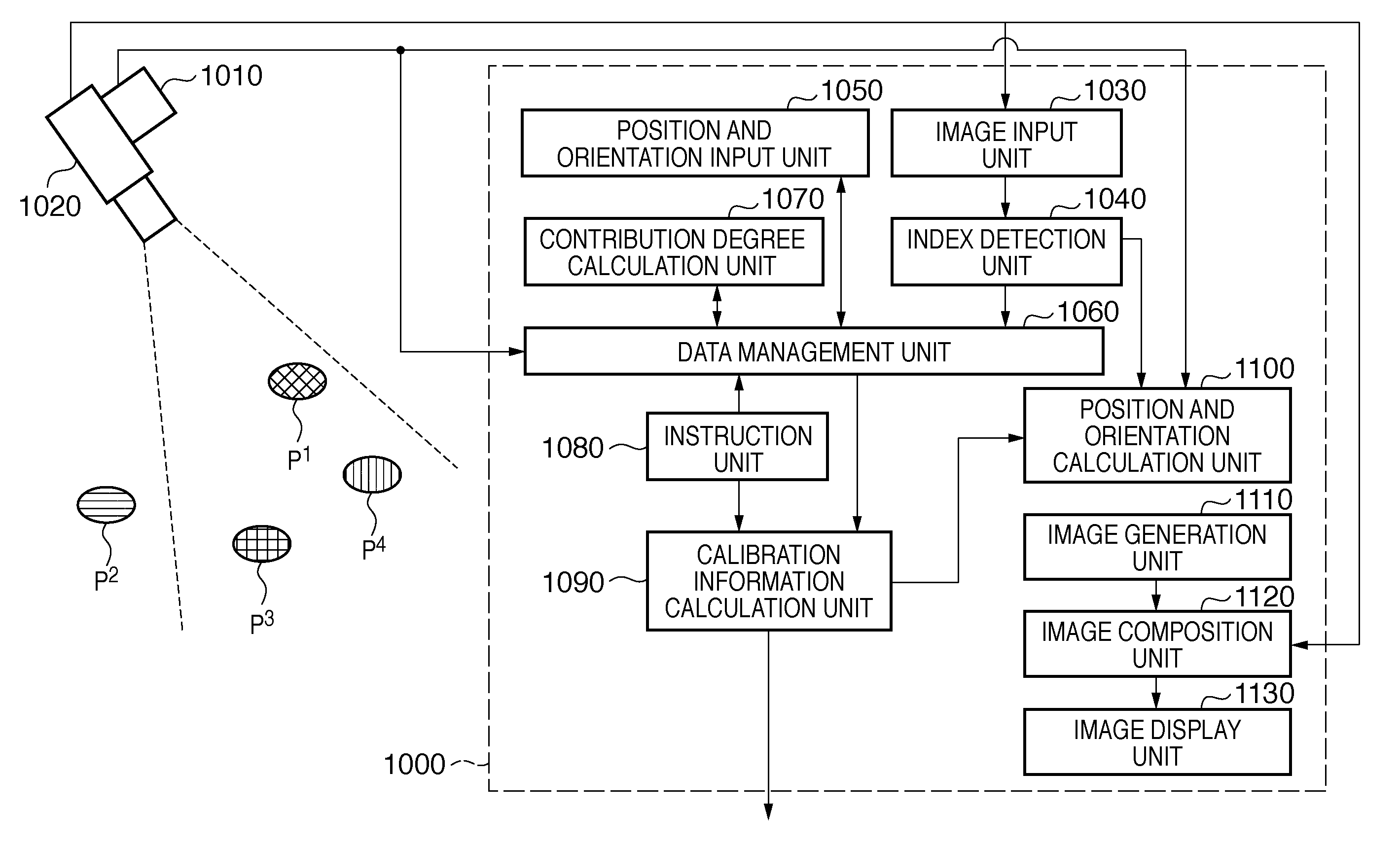
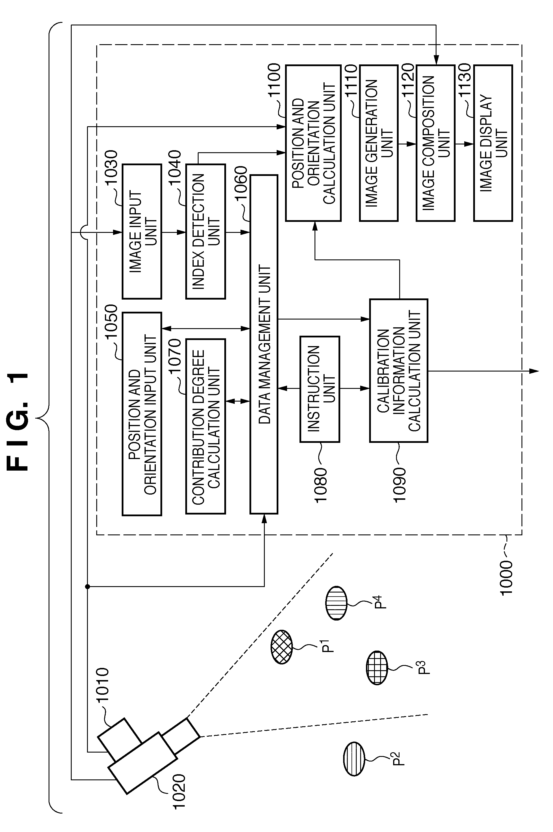
[0030]FIG. 1 is a block diagram showing an example of the functional arrangement of a system according to this embodiment. As shown in FIG. 1, a plurality of indices P1 to P4 are laid out on a physical space, and the system according to this embodiment includes an image sensing device 1020 which senses an image of this physical space, and an image processing apparatus 1000 which processes the sensed image of the image sensing device 1020. An orientation sensor 1010 as an object to...

second embodiment

[0117]In the first embodiment, as a feature amount associated with the image coordinates of a reference index, a point feature, i.e., the image coordinates of one point that represents a projected image of an index are used. As a reference index P, an index from which such point feature can be extracted is used. However, the type of reference index and that of feature amount associated with the image coordinates of the reference index are not limited to those.

[0118]For example, using, as a feature amount associated with the image coordinates of a reference index, a line feature used in a known position and orientation measurement apparatus (for example, see “D. G. Lowe: Fitting parameterized three-dimensional models to images, IEEE Transactions on PAMI, vol. 13, no. 5, pp. 441 to 450, 1991”), an index from which a line feature can be extracted (to be referred to as a line index hereinafter) may be used as a reference index.

[0119]For example, an error vector U is configured by errors...

third embodiment

[0120]The respective units that configure the image processing apparatus 1000 shown in FIG. 1 may be implemented by hardware components, or some or all of these units may be implemented by software. Note that some of components that configure the image processing apparatus 1000 are described as a main body which holds and manages data. Upon implementing such component by software, data described as those to be held and managed by that component may be stored in a memory of a computer which executes software corresponding to this component, and that component may manage these data.

[0121]FIG. 4 is a block diagram showing an example of the hardware arrangement of a computer applicable to the image processing apparatus 1000.

[0122]A CPU 401 controls the overall computer using computer programs (programs) and data stored in a RAM 402 and ROM 403, and executes the aforementioned processes as those to be implemented by the image processing apparatus 1000 to which this computer is applied.

[0...


PUM


Abstract

An index detection unit (1040) detects the coordinate values of indices in a sensed image sensed by an image sensing device (1020) attached with an orientation sensor (1010). A contribution degree calculation unit (1070) acquires contribution degrees according to a frequency at which the image sensing device (1020) is located to have an orientation indicated by orientation information included in the position and orientation information of the image sensing device (1020) at the time of image sensing. A data management unit (1060) generates sets of the coordinate values and orientation information measured by the orientation sensor (1010) at the time of sensing of the sensed image for respective indices. A calibration information calculation unit (1090) calculates an orientation of the orientation sensor (1010) with respect to the image sensing device (1020) using the position and orientation information, parameter values, and the sets generated for the respective indices.

Description

BACKGROUND OF THE INVENTION[0001]1. Field of the Invention[0002]The present invention relates to a correction technique of the position and orientation of an image sensing device.[0003]2. Description of the Related Art[0004]In recent years, studies about mixed reality (MR) that aims at seamless merging of a physical space and virtual space have been extensively made. An image display apparatus which presents MR is implemented by an apparatus having the following arrangement. That is, an apparatus displays an image by superimposing and rendering an image of the virtual space (for example, a virtual object rendered by computer graphics and text information) generated according to the position and orientation of an image sensing device such as a video camera on an image of the physical space sensed by the image sensing device.[0005]As an application of such image display apparatus, a navigation that superimposes names and guides of well-known buildings and the like included in an image...

Claims


Application Information

Patent Timeline
Patent Type & Authority Applications(United States)
IPC IPC(8): G09G5/00
CPCG06T2207/30204G06T7/0018G06T7/80
Inventor NAKAMURA, NAOHITO
Owner CANON KK
Learn More