Methods for driving electro-optic displays

a technology of electro-optic displays and displays, applied in the direction of electric digital data processing, instruments, computing, etc., can solve the problems of inadequate service life of these displays, preventing their widespread use, and gas-based electrophoretic media being susceptible to the same types of problems

Active Publication Date: 2009-08-06
E INK CORPORATION
View PDF3 Cites 258 Cited by
  • Summary
  • Abstract
  • Description
  • Claims
  • Application Information

AI Technical Summary

Benefits of technology

[0064]This method of the present invention may hereinafter for convenience be called the “double drive scheme” or DDS method of the present invention. As will readily be apparent from the foregoing discussion, the second drive scheme in this method is intended to be invoked when the display is to accept input from a stylus, pen, keyboard, mouse or similar input devic...

Problems solved by technology

Nevertheless, problems with the long-term image quality of these displays have prevented their widespread usage.
For example, particles that make up electrophoretic displays tend to settle, resulting in inadequate service-life for these displays.
Such gas-based electrophoretic media appear to be susceptible to the same types of problems due to particle settling as liquid-based electrophoretic media, when the media are used in an orientation which permits such settling, for example in a sign where the medium is disposed in a vertical plane.
Indeed, particle settling appears to be a more serious problem in gas-based electrophoretic media than in liquid-based ones, since the lower viscosity of gaseous suspending fluids as compared with liquid ones allows more rapid settling of the electrophoretic particles.
However, inevitably there is some error in writing images on an impulse-driven display.
Other types of mechanical non-uniformity may arise from inevitable variations between different manufacturing batches of medium, manufacturing tolerances and materials variations.(f) Voltage Errors; The actual impulse applied to a pi...

Method used


Image

  • Methods for driving electro-optic displays
  • Methods for driving electro-optic displays
  • Methods for driving electro-optic displays

Examples


Embodiment Construction

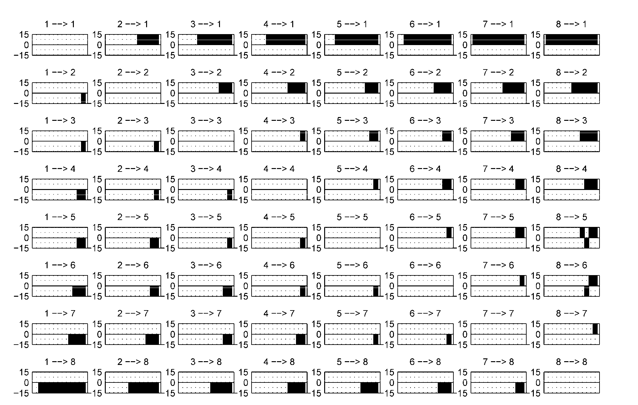
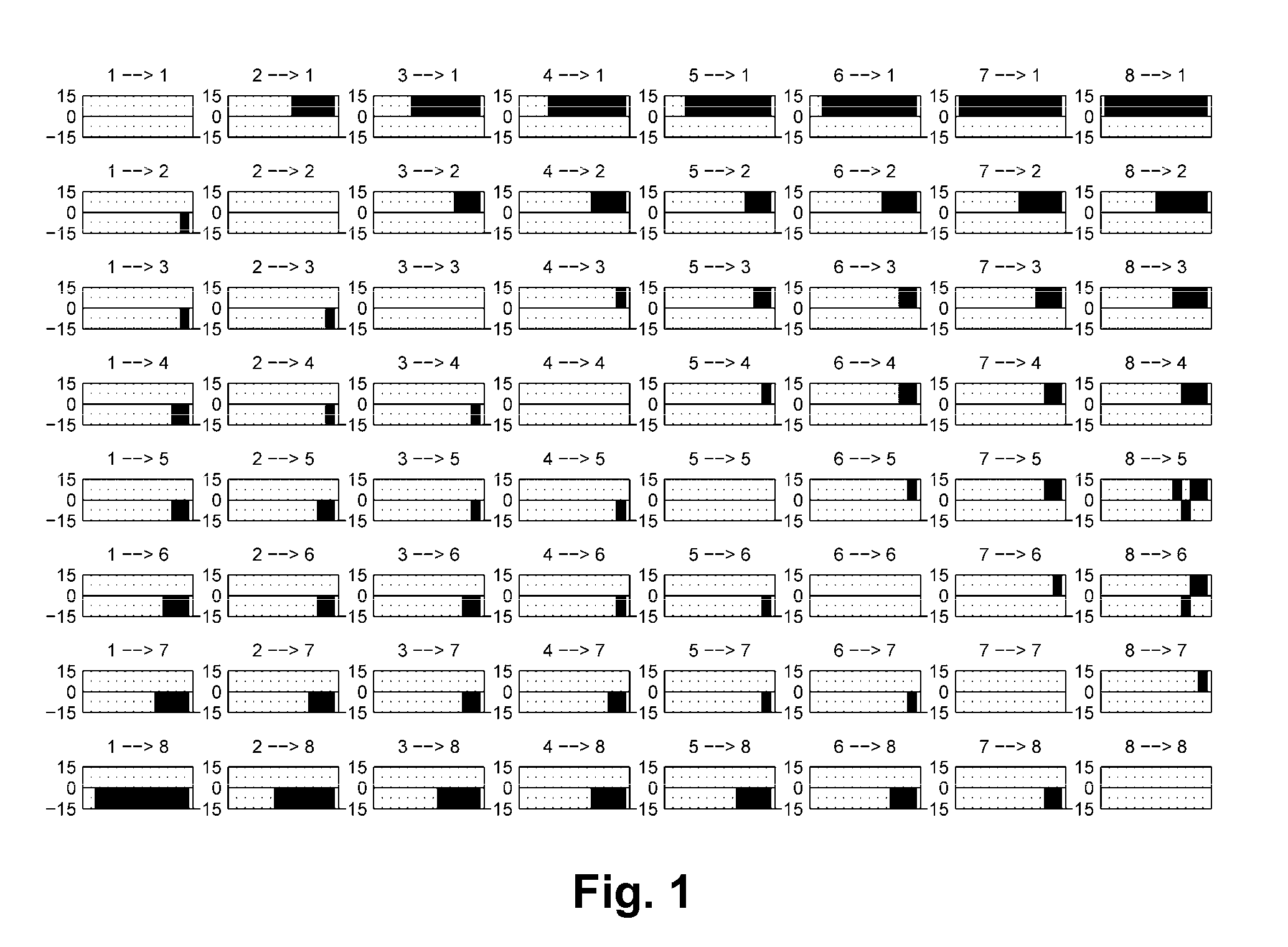
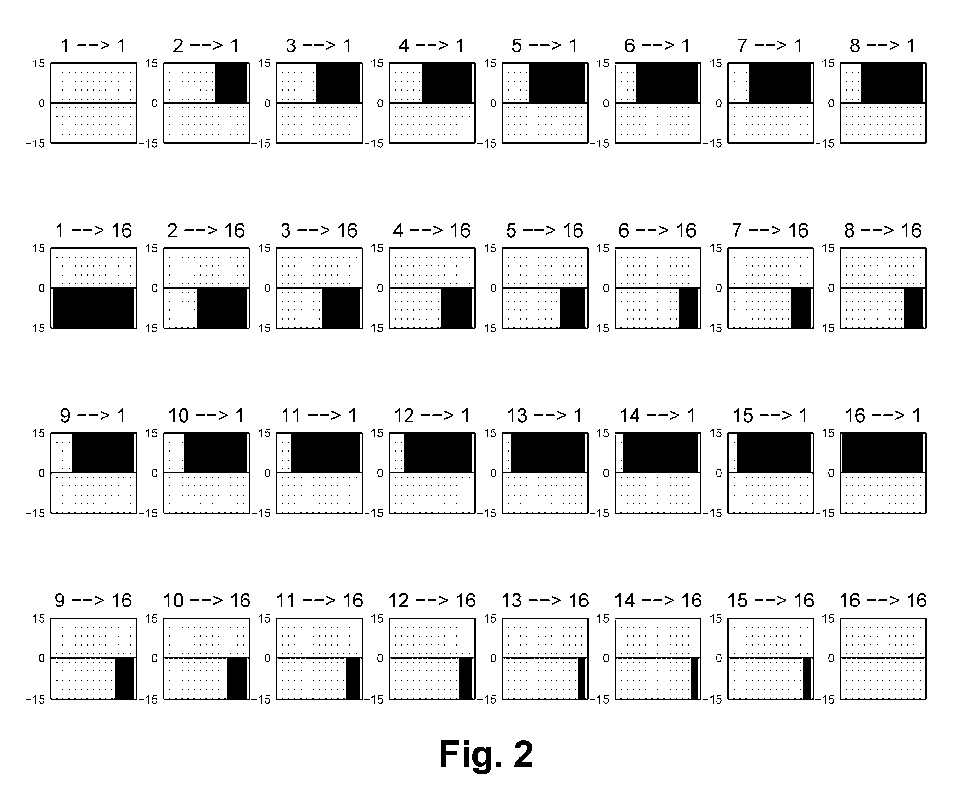
[0075]As already indicated, this invention provides a method of driving a multi-pixel bistable electro-optic display. This method uses a first drive scheme capable of effecting transitions between all of the gray levels which can be displayed by the pixels; and a second drive scheme which contains only transitions ending at one of the extreme optical states of the pixels. The second drive scheme is intended to allow for rapid response of the display to user input, for example the user “writing” with a stylus on a display which incorporates a touch screen; note that such a touch screen may lie in front of or behind the electro-optic medium from the perspective of the user.

[0076]A standard gray scale drive scheme, such as may be used as the first drive scheme in this method, has an update time that is two to three times the length of a “saturation pulse” where a saturation pulse is defined as the pulse having the duration required to apply an impulse that will drive the display from o...


PUM


Abstract

A bistable electro-optic display having a plurality of pixels each of which is capable of displaying at least three optical states, including two extreme optical states, is driven by the method comprising a first drive scheme capable of effecting transitions between all of the gray levels which can be displayed by the pixels; and a second drive scheme which contains only transitions ending at one of the extreme optical states of the pixels.

Description

REFERENCE TO RELATED APPLICATIONS[0001]This application claims benefit of Application Ser. No. 61 / 044,584, filed Apr. 14, 2008. This application is also a continuation-in-part of copending application Ser. No. 11 / 425,408, filed Jun. 21, 2006 (Publication No. 2006 / 0232531), which itself is a divisional of application Ser. No. 10 / 814,205, filed Mar. 31, 2004 (now U.S. Pat. No. 7,119,772), which claims benefit of (i) Application Ser. No. 60 / 320,070, filed Mar. 31, 2003; (ii) Application Ser. No. 60 / 320,207, filed May 5, 2003; (iii) Application Ser. No. 60 / 481,669, filed Nov. 19, 2003; (iv) Application Ser. No. 60 / 481,675, filed Nov. 20, 2003; and (v) Application Ser. No. 60 / 557,094, filed Mar. 26, 2004.[0002]This application is related to:[0003](a) U.S. Pat. No. 6,504,524;[0004](b) U.S. Pat. No. 6,512,354;[0005](c) U.S. Pat. No. 6,531,997;[0006](d) U.S. Pat. No. 6,995,550;[0007](e) U.S. Pat. Nos. 7,012,600 and 7,312,794, and the related Patent Publications Nos. 2006 / 0139310 and 2006 / 01...

Claims


Application Information

Patent Timeline
IPC IPC(8): G09G5/10
CPCG09G3/2011G09G2320/0285G09G2320/0204G09G3/344
Inventor SJODIN, THEODORE A.
Owner E INK CORPORATION
Why Eureka
Try Eureka