
Level shifter circuit and method thereof

a shifter circuit and level technology, applied in logic circuits, logic circuit coupling/interface arrangements, pulse techniques, etc., can solve the problems of increasing power consumption of semiconductor devices, and achieve the effect of reducing the transition time of output signals

Inactive Publication Date: 2007-08-16
SAMSUNG ELECTRONICS CO LTD
View PDF10 Cites 21 Cited by
  • Summary
  • Abstract
  • Description
  • Claims
  • Application Information

AI Technical Summary

Benefits of technology

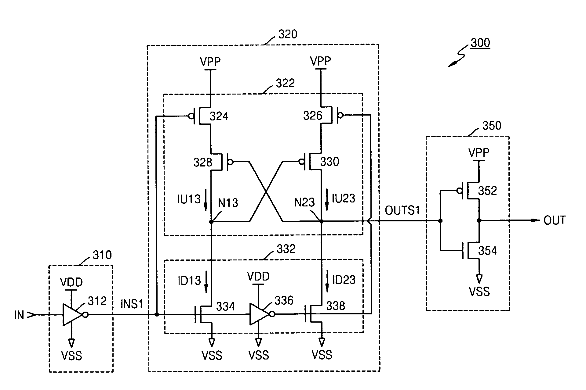
[0034]Another example embodiment of the present invention is directed to a level shifter circuit capable of reducing a transition time of an output signal during a transition of an input signal at a lower voltage to the output signal at a higher voltage.

Problems solved by technology

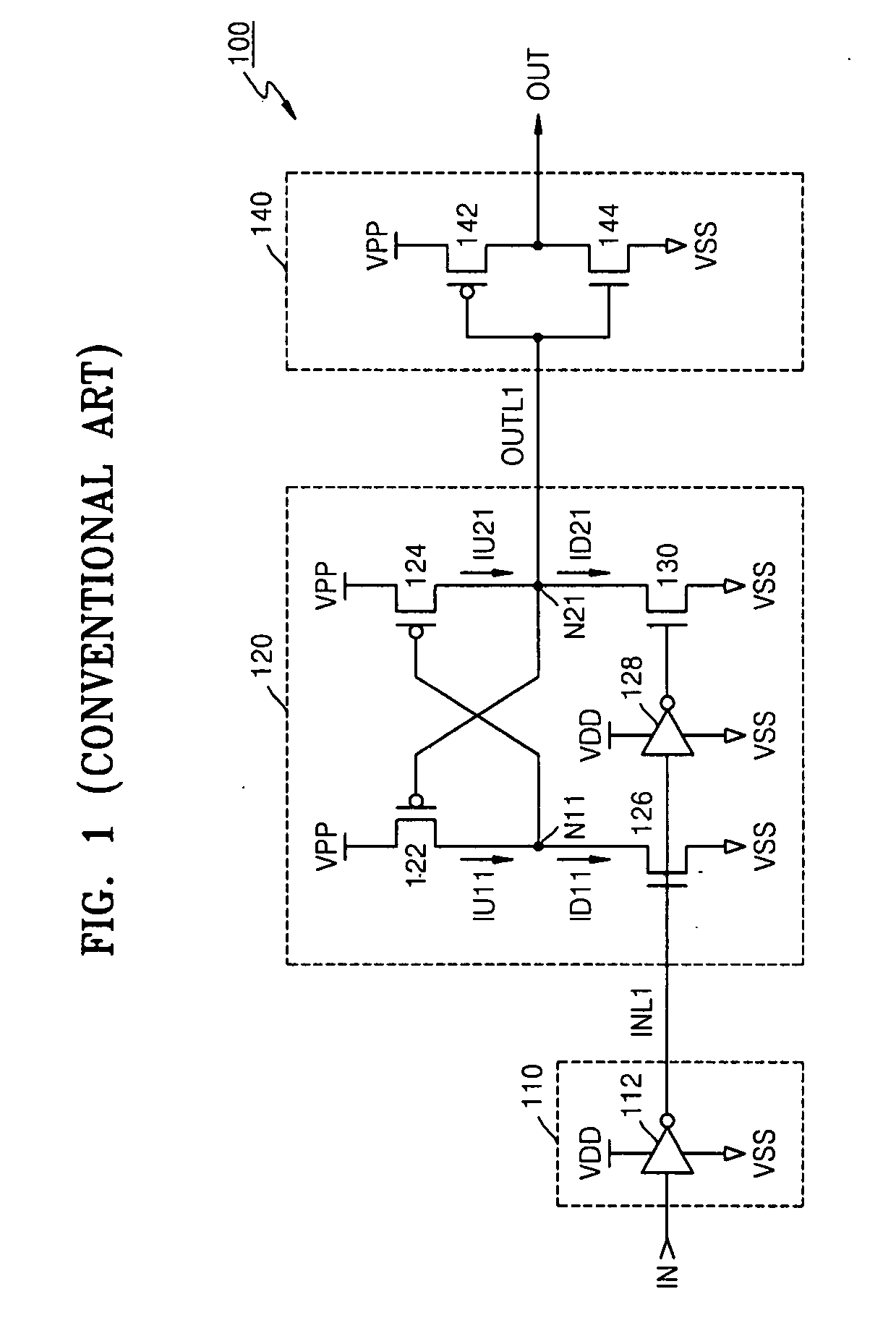
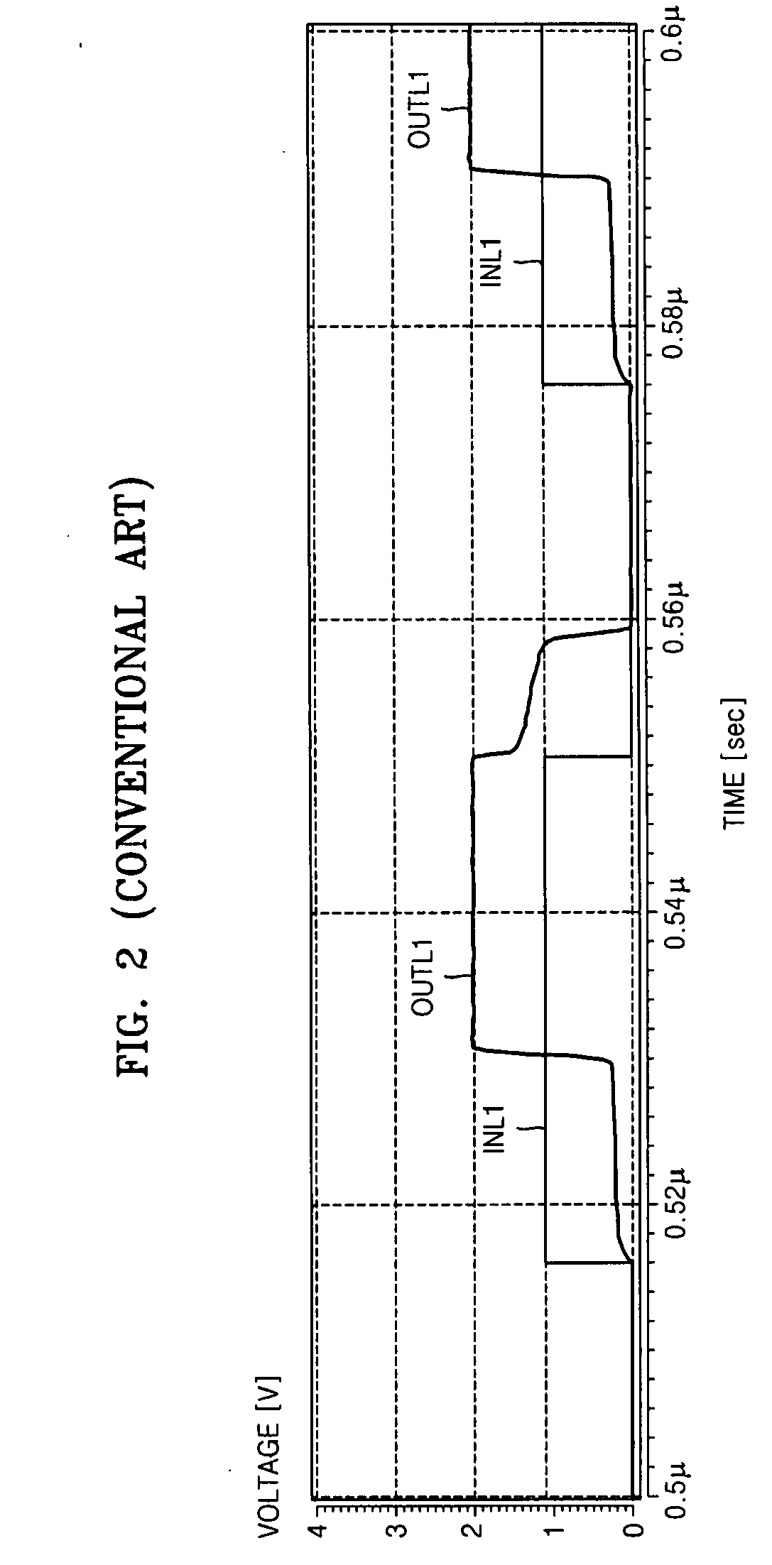
Accordingly, a relatively high amount of leakage current may be generated in the level shifter circuit 120, which may increase power consumption of the semiconductor device 100.

Method used


Image

  • Level shifter circuit and method thereof
  • Level shifter circuit and method thereof
  • Level shifter circuit and method thereof

Examples


Embodiment Construction

[0047]Detailed illustrative example embodiments of the present invention are disclosed herein. However, specific structural and functional details disclosed herein are merely representative for purposes of describing example embodiments of the present invention. Example embodiments of the present invention may, however, be embodied in many alternate forms and should not be construed as limited to the embodiments set forth herein.

[0048]Accordingly, while example embodiments of the invention are susceptible to various modifications and alternative forms, specific embodiments thereof are shown by way of example in the drawings and will herein be described in detail. It should be understood, however, that there is no intent to limit example embodiments of the invention to the particular forms disclosed, but conversely, example embodiments of the invention are to cover all modifications, equivalents, and alternatives falling within the spirit and scope of the invention. Like numbers may ...


PUM


Abstract

A level shifter circuit and method thereof are provided. The example level shifter circuit may include a pull-up drive unit driving an output node from a first voltage to a second voltage in response to an input signal, a target voltage for the second voltage higher than a target voltage for the first voltage and the input signal based on the first voltage and a third voltage and a pull-down drive unit driving the output node to the third voltage in response to the input signal, the pull-up and pull-down drive units adjusting current levels of at least one of a pull-up current flowing through the pull-up drive unit and a pull-down current flowing through the pull-down drive unit based on whether the pull-up drive unit and the pull-down drive unit are operating concurrently. The example method may include pull-up driving an output node from a first voltage to a second voltage in response to an input signal, a target voltage for the second voltage higher than a target voltage for the first voltage and the input signal based on the first voltage and a third voltage, pull-down driving the output node to the third voltage in response to the input signal, determining whether the pull-up and pull-down driving operations are performed concurrently and adjusting current levels of at least one of a pull-up current and a pull-down current based on the determining step.

Description

[0001]This application claims the benefit of Korean Patent Application No. 10-2006-0040391, filed on May 4, 2006, and Korean Patent Application No. 10-2006-0014742, filed on Feb. 15, 2006, in the Korean Intellectual Property Office, the disclosure of which is incorporated herein in its entirety by reference.BACKGROUND OF THE INVENTION[0002]1. Field of the Invention[0003]Example embodiments of the present invention relate generally to a level shifter circuit and method thereof, and more particularly to a level shifter circuit and method of reducing leakage current.[0004]2. Description of the Related Art[0005]As power consumption of a semiconductor device (e.g., a dynamic random access memory (DRAM)) decreases, an external supply voltage may be reduced. Accordingly, a level shifter circuit for transforming a lower voltage to a higher voltage may be used to provide a lower external voltage to an internal circuit of the semiconductor device using the “boosted” voltage. Thus, the level s...

Claims


Application Information

Patent Timeline
Patent Type & Authority Applications(United States)
IPC IPC(8): H03K19/0175
CPCH03K19/018528
Inventor YANG, HUI-KAPKANG, YOUNG-GUCHUN, KI-CHULSEO, EUN-SUNGKIM, MI-JO
Owner SAMSUNG ELECTRONICS CO LTD
Learn More